
User Manual
This document is not allowed to
transmit without ZTE Corporation
’s
permission
©ZTE CORPORATION All rights reserved
16
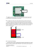
3.1.11
Charging
MG2639 V3 module provides the charging of Li battery through the design of external circuits.
See section 4.5 for external reference design.
Table 3-11 Charging interface signal definitions
Classification
No. Definitions
I/O
Description
Remarks
Charging
23
BATSNS
Input
Charging control
Battery voltage
detection
24
ISENSE
Input
Charging control
Battery current
detection
25
VCHG
Input
Power
Charging power supply
26
CHR_LDO
Output
Charging control Charging on/off
27
GATDRV
Output
Charging control
Charging dynatron
control
Note: the software doesn’t support this interface by default, therefore it requires
customization.
3.1.12
SIM card interface
MG2639_V3 module supports the SIM card interface conforming to ISO 7816-3 standard, and it
supports SIM cards with two different standards: 1.8V and 3.0V.
Users should note that the SIM card’s electrical interface should be defined exactly the same as
the SIM card socket.
Table 3-12 SIM card interface signal definitions
Classification
No.
Definitio
ns
I/O
Description
Remarks
SIM
14
VSIM
Output
SIM card voltage
1.8V/3V, Max. output
current 30 mA
11
SIM_RST
Output
SIM card reset
12
SIM_CLK
Output
SIM card clock
13
SIM_DATA
I/O
SIM card data
3.1.13
Audio interface
MG2639_V3 module supports 2CH audio signal inputs/outputs. The two MIC inputs are internally
capacitive coupled with the offset voltage, and directly connected to the receiver. See the audio
interface signals in the table 3-2: