background image


21    

Configuring the BIOS
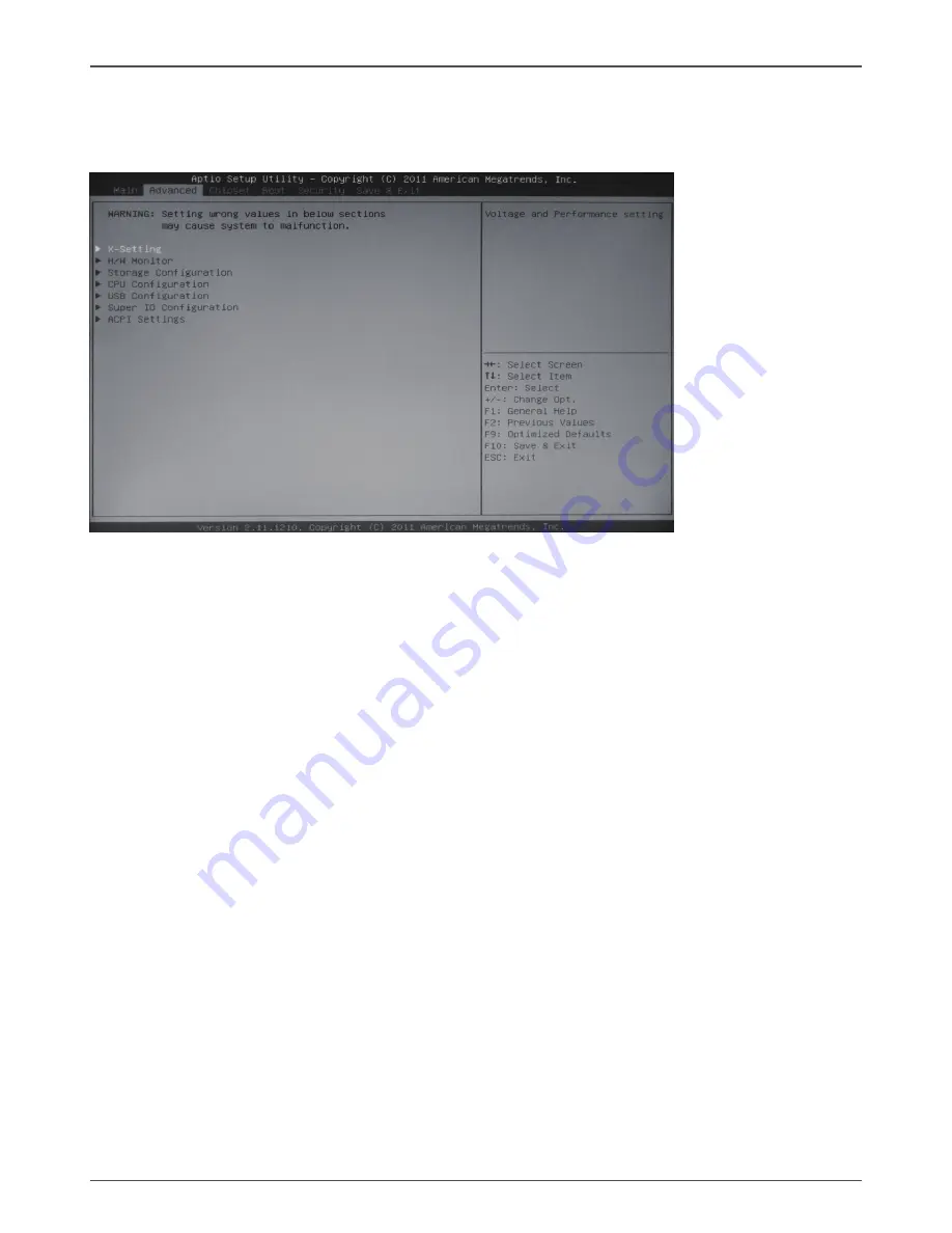
Advanced Menu

The Advanced menu items allow you to change the setting for the CPU and other 

system devices. Press <enter> to display the configuration options:

X-Setting

The X-Setting menu items show the settings of CPU, memory and so on.

CPU Configuration

The items in this submenu show the CPU-related information that the BIOS 

automatically detects.

GPU Boost

Use this item to adjust graphics configuration.

Memory Timing Configuration

Use this item to monitor memory timing configuration.

H/W Monitor


The items in this menu allow you to monitor the hardware status. Press <enter>to 

display the configuration options:

CPU FAN Control Mode


Use this item to select CPU FAN Control mode.

Start Temperature


Use this item to select the start temperature.

Start Fan Duty


Use this item to select the start fan dutycycle.

Highest Fan Duty


Use this item to select the highest fan dutycycle.

SYS Fan Control Mode


Use this item to select SYS FAN Control mode.

Duty Cycle

Use this item to select the fan dutycycle.

Содержание Supreme H67ITX series

Страница 1: ......

Страница 2: ...R OR AN EXPERIENCED AUDIO TELEVISION TECHNICIAN NOTE Connecting this device to peripheral devices that do not comply with Class B requirements or using an unshielded peripheral data cable could also r...

Страница 3: ...ting Switches 14 24 pin ATX Power Connector PW1 15 4 pin ATX_12V power connector PW2 15 COM Header CN4 Optional 16 Front Panel Header FP1 16 USB Headers FP_U1 FP_USB3_1 17 Front Pannel Audio Header FP...

Страница 4: ...lts 28 Save as User Defaults 28 Restore User Defaults 28 Launch EFI Shell from filesystem device 28 Flash Update Procedure 28 Installing Drivers and Software 29 Drivers Installation 29 Realtek HD Audi...

Страница 5: ...wo ports on the back panel two via the USB brackets connected to the internal USB header v Supports USB 2 0 protocol up to 480 Mbps transmission rate q USB 3 0 ports v Supports hot plug and play v Fou...

Страница 6: ...CUDATM technology v One HDMI port and one DVI I port output support Note Support two simultaneous independent displays from DVI I DVI I HDMI DP q PCI Express Interface v Supports PCI Express 2 0 v Wa...

Страница 7: ...om and Figure 3 shows the back panel connectors Figure 1 Board Layout 1 CPU Fan Connector CPUFAN3 2 DDRIII SO DIMM Sockets DDR3_1 2 3 SYS Fan Connector SYSFAN3 4 4 24 pinATX Power Connector PW1 5 USB...

Страница 8: ...D indicators Speed LED Activity LED Activity LED Status Descritption Off No link Orange Linked Blinking Data activity Speed LED Status Description Off Speed 10 Mbps Green Speed 100 Mbps Orange Speed 1...

Страница 9: ...rs can install one or two WiFi antennas to the motherboard 3 Users can bend or rotate the WiFi antennas to the best receiving direction according to the picture below 115XLM REMOVE 1 5V 1 5V 9 Port 2...

Страница 10: ...otherboard v Installing the I O Shield v Securing the Motherboard into the Chassis v Installing an mSATA SSD module optional q Connecting cables and setting switches Safety Instructions To reduce the...

Страница 11: ...U installation components 1 Unhook the socket lever by pushing down and away from the socket 2 Lift the socket lever and the load plate to fully open position 3 Use your thumb and forefinger to lift t...

Страница 12: ...be at least one memory bank populated to ensure normal operation Refer to the following recommendations to install memory modules Note that a memory module has a notch so it can only fit in one direc...

Страница 13: ...from dust and foreign objects and promotes correct airflow within the chassis Before installing the motherboard install the I O shield from the inside of the chassis Press the I O shield into place a...

Страница 14: ...all the mSATA SSD module according to the following instructions 1 Locate the Mini PCIe slot of the bottom and insert an mSATA SSD into the slot at a 45 degree angle 2 Gently press down on the mSATA S...

Страница 15: ...nectors v 24 pin ATX Power Connector PW1 v 4 pin ATX_12V Power Connector PW2 q Internal Headers Connectors v COM Header CN4 Optional v Front Panel Header FP1 v USB Headers FP_U1 FP_USB3 1 v Front Pann...

Страница 16: ...ure PW1 Pin Definition Pin Signal Pin Signal 1 3 3V 13 3 3V 2 3 3V 14 12V 3 GND 15 GND 4 5V 16 PS_ON 5 GND 17 GND 6 5V 18 GND 7 GND 19 GND 8 PWROK 20 5V 9 5V_AUX 21 5V 10 12V 22 5V 11 12V 23 5V 12 3 3...

Страница 17: ...the hard disks q RST SW Attach the Reset switch cable from the front panel of the case to these two pins The system restarts when the RESET switch is pressed Note Some chassis do not have all four cab...

Страница 18: ...the same as the pin assignment on the mainboard header To find out if the chassis you are buying supports a front audio connector please contact your dealer FP_U1 Pin Definition PIN Assignment PIN Ass...

Страница 19: ...transfer rate up to 3 0 Gb s each and two SATA III ports SATA1 2 with maximum tranansfer rate up to 6 0 Gb s each SPK1 Pin Definition PIN Assignment 1 VCC 2 NC 3 NC 4 SPK SATA Pin Definition Pin Signa...

Страница 20: ...ne mSATA SSD Please refer to page 13 to install the mSATA SSD module PCI Express x4 Slot PCIE_X4 There is one PCI Express x4 slot that is designed to accommodate less bandwidth intensive cards such as...

Страница 21: ...OST Pressing Del takes you to the BIOS Setup Utility Note 1 We reserve the right to update the BIOS version presented in the manual The BIOS pictures shown in this section are for reference only 2 It...

Страница 22: ...s configuration q Memory Timing Configuration Use this item to monitor memory timing configuration H W Monitor The items in this menu allow you to monitor the hardware status Press enter to display th...

Страница 23: ...dows XP operating system set this item to Enable for legacy operating system such as Windows NT4 0 q Execute Disable Bit When disabled forces the XD feature flag to always return 0 defaults choose Ena...

Страница 24: ...et device power up delay Super IO Configuration The items in this menu allow you to configure NCT5577D Super IO Chipset q PS2 Keyboard Mouse Swap When set to Enabled the PS2 port can support either ke...

Страница 25: ...itate Graphic Adapter q DVMT FIXED Memory Use this item to set the size for DVMT FIXED Memory q Render Standby Use this item to enable or disable Render Standby q IGD Multi Monitor Use this item to en...

Страница 26: ...NumLock state On or Off q Quiet Boot When set to Disabled displays normal POST message When set to Enabled displays OEM Logo instead of POST messages q Fast Boot Enable or disable boot with initializa...

Страница 27: ...ser Password 1 Select the item Administrator User Password and press Enter 2 From the password box type a password composed of at least six letters and or numbers then press Enter 3 Confirm the passwo...

Страница 28: ...de changes to fields other than system date system time and password the BIOS asks for a confirmation before exiting Save Changes and Reset Select this item and press Enter to reset the system after s...

Страница 29: ...ESET the computer during the flash process If you are not sure how to upgrade the BIOS please take your computer to an Authorized Service Center and have a trained technician do the work for you Disca...

Страница 30: ...h your motherboard contains the following software and drivers q Intel Chipset Driver q HDA Sound Driver q Intel Graphics Driver q Nvidia Graphics Driver q Ethernet PCI E Driver q VIA USB 3 0 Controll...

Страница 31: ...30 Intel H67 ITX series Motherboard 2 Left click Intel Chipset Driver begin loading...

Страница 32: ...31 Installing Drivers And Software 3 Left click HDA sound driver begin loading 4 Left click Intel Graphics Driver begin loading...

Страница 33: ...32 Intel H67 ITX series Motherboard 5 Left click Nvdia Graphics Driver begin loading...

Страница 34: ...33 Installing Drivers And Software 6 Left click Ethernet PCI E Driver begin loading...

Страница 35: ...34 Intel H67 ITX series Motherboard 7 Left click VIA USB 3 0 Controller Driver begin loading Note USB 3 0 port would not work in POST CMOS setup and DOS mode...

Страница 36: ...35 Installing Drivers And Software...

Страница 37: ...36 Intel H67 ITX series Motherboard 8 Left click Intel Management Engine begin loading...

Страница 38: ...37 9 Left click Azurewave WIFI driver begin loading Installing Drivers And Software...

Страница 39: ...38 Intel H67 ITX series Motherboard 10 Left click Bluetooth driver begin loading...

Страница 40: ...39 Installing Drivers And Software At last you can enter Computer Management that provides information about the hardware devices on this motherboard to check if the driver installation is complete...

Страница 41: ...on and the control panel will appear Sound Effect After clicking on the Sound Effect tab 3 sections Environment Equalizer and Karaoke are available for selection Environment Simulation You will be abl...

Страница 42: ...tly used for your quick enjoyment How to Use Other than the buttons Pop Live Club Rock shown on the page to pull down the arrow in Others you will find more optimized settings available to you Karaoke...

Страница 43: ...o you to create your favorite sound effect in one single tool Playback control Mute You may choose to mute single or multiple volume controls or to completely mute sound output Tool Show the following...

Страница 44: ...mute single or multiple volume controls or to completely mute sound input Tool Show the following volume controls This is to let you freely decide which volume control items to be displayed Advanced...

Страница 45: ...in functions Instead now each jack is able to be chosen to perform either output i e playback function or input i e Recording function we call this Retasking Audio I O aims to help you setting jacks a...

Страница 46: ...any available jack Step 2 Dialogue Connected device will pop up for your selection Please select the device you are trying to plug in If the device is being plugged into the correct jack you will be...

Страница 47: ...o called AC 97 jacks If so please check this item to disable front panel jack detection Enable auto popup dialogue when device has been plugged in Once this item checked the dialog Connected device wo...

Страница 48: ...ecommended while playing HD Audio Output Source Output digital audio source The digital audio format such as wav mp3 midi etc will come out through S PDIF Out Speaker Calibration After you have succes...

Страница 49: ...You will get the best quality if you chose 90 position which we recommend you to use this effectively means that you speak right into the microphone Note A Stereo Microphone is required when using Be...

Страница 50: ...dio Demo The section 3D Audio Demo grants you another possibility to enjoy your sound The Audio Demo allows you to listen to sound in an extraordinary way Information This section provides information...

Страница 51: ...our computer then press Delete to enter BIOS SETUP UTILITY 2 Use the arrow key to select Advanced menu When enter the Advanced menu select the Item Storage Configuration 3 Press Enter to display Stora...

Страница 52: ...orage Technology RAID BIOS menu 2 The main Intel R Rapid Storage Technology RAID BIOS menu appears 3 Use the arrow keys to move the color bar and navigate through the items Creating a RAID set 1 In th...

Страница 53: ...D 3 Press Enter to confirm the creation of the RAID set A dialogue box appears to confirm the action Press Y to confirm otherwise press N 4 The following screen appears displaying the relevant informa...

Страница 54: ......

Отзывы: