background image

6


GeForce 8100/8200/8300 series Motherboard 

PIN 

SIGNAL

GND 

TXP   

TXN 

GND

RXN

RXP

GND

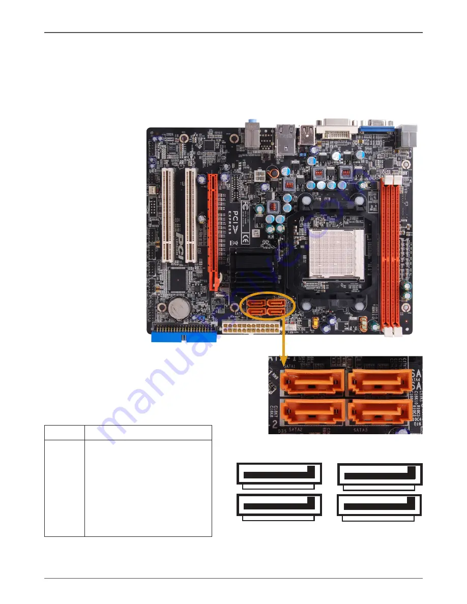
SATA-/SATA-/SATA3/SATA4 

- Pin Definition

Connecting Serial ATA Cables(SATA-1~SATA-4 Optional)

The Serial ATA II connector is used to connect the Serial ATA II device to the motherboard. 
These connectors support the thin Serial ATA II cables for primary storage devices. The 
current Serial ATA II interface allows up to 3Gb/s data transfer rate. There are four serial 

ATA connectors on the motherboard that support AHCI and RAID configurations.

SATA-

SATA-3

SATA-4

SATA-

1

1

1

1

Содержание GeForce 8100

Страница 1: ......

Страница 2: ...ONNECT THE EQUIPMENT INTO AN OUTLET ON A CIRCUIT DIFFERENT FROM THAT OF THE RECEIVER CONSULT THE DEALER OR AN EXPERIENCED AUDIO TELEVISION TECHNICIAN NOTE Connecting this device to peripheral devices...

Страница 3: ...Setting Switches 12 24 pin ATX Power PW1 13 4 pin ATX 12V Power PW2 14 SPK Connector 14 SPDIF In Out Header optional 15 Connecting Serial ATA Cables 16 Connecting Internal Headers 17 Front Panel Head...

Страница 4: ...ntrol 33 Audio I O 34 Speaker Configuration 35 Global Connector Settings 36 S PDIF 36 Speaker Calibration 37 Microphone 38 Noise Suppression 38 Beam Forming 38 Acoustic Echo Cancellation 38 Audio Demo...

Страница 5: ...up from S1 v Supports USB 2 0 protocol up to 480 Mbps transmission rate q Onboard Serial ATA II v Independent DMA operation on four ports optional v Data transfer rates of 300Mb s q Onboard LAN v LAN...

Страница 6: ...rmance with GeForce Boost and provide intelligent power management with HybridPowerTM v DVI output support optional v HDMI support through a DVI HDMI dongle optional q Expansion Slots v One PCI Expres...

Страница 7: ...YS Fan connector 14 CPU fan connector 5 SPDIF connector 15 SATAconnector 6 Front panel audio Connector 16 24 pinATX Power Connector 7 PCI Slots 17 Chipset 8 PCI Express x16 slot 18 J1H1 Clear CMOS jum...

Страница 8: ...n Line In Line In Green Line Out Front Speaker Out Front Speaker Out Front Speaker Out Pink Mic In Mic In Mic In Mic In Orange Center Subwoofer Center Subwoofer Black Rear Speaker Out Rear Speaker Out...

Страница 9: ...injury always follow basic safety precations Remember to remove power from your computer by disconnecting the AC main source before removing or installing any equipment from to the computer chassis P...

Страница 10: ...t be seen Please note that any deviation from the correct installation procedures may cause permanent damage to your motherboard 4 Press the CPU down firmly into the socket and close the lever As the...

Страница 11: ...ations for installing memory See Figure 1 on page 6 for the location of the memory slots q One DIMM You can install the DIMM into any slot q Two DIMMs Install into slots 1 and 2 The idea is to run on...

Страница 12: ...re that the CPU fan assembly has enough clearance for the chassis covers to lock into place and for the expansion cards Also make sure the CPU Fan assembly is aligned with the vents on the covers Inst...

Страница 13: ...herboard Connecting Cables and Setting Switches This section takes you through all the connections and switch settings necessary on the motherboard See Figure 1 to locate the connectors and jumpers re...

Страница 14: ...the motherboard Firmly plug the power supply cable into the connector and make sure it is secure Table 1 PW1 Pin Assignments Connector Pin Signal Pin Signal 1 3 3V 13 3 3V 2 3 3V 14 12V 3 GND 15 GND 4...

Страница 15: ...pin ATX 12V power connection is used to provide power to the CPU Align the pins to the connector and press firmly until seated PIN Assignment 1 VCC 2 NC 3 NC 4 SPK SPK Pin Definition 1 2 3 4 PIN Assi...

Страница 16: ...r provides a SPDIF Sony Philips Digital Interface Input output to digital multimedia device through coaxial connector SPDIF Pin Definition PIN Assignment 1 SPDIF in 2 SPDIF out 3 3 3V 4 3 3V 5 NC 6 NC...

Страница 17: ...Optional The SerialATAII connector is used to connect the SerialATAII device to the motherboard These connectors support the thin SerialATAII cables for primary storage devices The current SerialATAII...

Страница 18: ...connectors to the corresponding pins q PWR SW Attach the power button cable from the case to these two pins Pressing the power button on the front panel turns the system on and off rather than using t...

Страница 19: ...4 Pin Definition 1 2 9 10 USB Headers This motherboard contains four USB 2 0 ports that are exposed on the rear panel of the chassis Figure 2 The motherboard also contains four 10 pin internal header...

Страница 20: ...header your chassis must have front audio con nector Also please make sure the pin assignment on the cable is the same as the pin assignment on the mainboard header To find out if the chassis you are...

Страница 21: ...herboard SYS FAN Connector Sense 12V GND Fan Connections There are two fan connections on the motherboard The fan speed can be detected and viewed in the PC Health Status section of the CMOS Setup CPU...

Страница 22: ...be sure that it is fully seated Secure the card s metal bracket to the chassis back panel with the screw used to hold the blank cover PCI Express x16 Slots There is one PCI Express x16 slot reserved...

Страница 23: ...hardware Before using your computer make sure all jumpers and DRAM modules are set correctly Refer to this chapter whenever in doubt Notice 1 Be sure to save the CMOS setting when exit the CMOS 2 If t...

Страница 24: ...nagement features The settings made in the Setup Utility affect how the computer performs Before using the Setup Utility ensure that you understand the Setup Utility options This chapter provides expl...

Страница 25: ...0 Save Exit Setup Time Date Hard Disk Type Note The sample BIOS Setup Menu included here only shows a typical case and may not be exactly the same as the one on your unit Note that a brief description...

Страница 26: ...Exit Without Abandons all CMOS value changes and exits setup Saving Standard CMOS Features The items in Standard CMOS Setup Menu are divided into 10 categories Each category includes one or more setu...

Страница 27: ...chipset registers These registers control most of the system options in the computer This section allows you to configure the system based on the specific features of the installed chipset This chipse...

Страница 28: ...ity Option from BIOS Features Setup menu you will be prompted for the password only when you enter BIOS Setup Supervisor Password has higher priority than User Password You can use Supervisor Password...

Страница 29: ...ype AWDFLASH ENTER 4 Enter the file name of the new BIOS 5 The question Do you want to save BIOS Y N is displayed Press N if there is no need to save the existing BIOS Press Y if a backup copy of the...

Страница 30: ...n your system setup the install disk may automatically run the install setp exe and pop up a menu If it does not run go to My Computer and click on the CD to open Usually you should install the Nvidia...

Страница 31: ...icon and the control panel will appear Sound Effect After clicking on the Sound Effect tab 3 sections Environment Equalizer and Karaoke are available for selection Environment Simulation You will be...

Страница 32: ...nt How to Use Other than the buttons Pop Live Club Rock shown on the page to pull down the arrow in Others you will find more optimized settings available to you Karaoke Mode Karaoke mode brings Karao...

Страница 33: ...age to you to create your favorite sound effect in one single tool Playback control Mute You may choose to mute single or multiple volume controls or to completely mute sound output Tool Show the foll...

Страница 34: ...controls or to completely mute sound input Tool Show the following volume controls This is to let you freely decide which volume control items to be displayed Advanced controls Advanced control is a M...

Страница 35: ...tions Instead now each jack is able to be chosen to perform either output i e playback function or input i e Recording function we call this Retasking Audio I O aims to help you setting jacks as you w...

Страница 36: ...select the device you are trying to plug in If the device is being plugged into the correct jack you will be able to find the icon beside the jack changed to the one that is same as your device If not...

Страница 37: ...ystem are so called AC 97 jacks If so please check this item to disable front panel jack detection Enable auto popup dialogue when device has been plugged in Once this item checked the dialog Connecte...

Страница 38: ...ital audio source The digital audio format such as wav mp3 midi etc will come out through S PDIF Out Speaker Calibration After you have successfully plugged in speakers and assigned to the right jacks...

Страница 39: ...rded You will get the best quality if you chose 90 position which we recommend you to use this ef fectively means that you speak right into the microphone Note A Stereo Microphone is required when usi...

Страница 40: ...o grants you another possibility to enjoy your sound The Audio Demo allows you to listen to sound in an extraordinary way Information This section provides information about your current system audio...

Страница 41: ...User Manual Setting up the BIOS 1 Setting your computer then press Delete to enter the Bios setup The BIOS CMOS Setup Utility window appears 2 Use the arrow keys to select Integrated Peripherals then...

Страница 42: ...AID Config window enable RAID then enable the disks that you want to use as RAID disks 5 Press F10 to save the configuration and exit The PC reboots 6 Enter the RAID BIOS Setup by pressing F10 when pr...

Страница 43: ...ation 4 If RAID 0 Striping is selected you can manually set the striping block size in the Striping Block field use the UP or DOWN ARROW ey to set the Striping Block size The KB is standard unit of St...

Страница 44: ...f the hard drives contain previously created RAID array you need to press Y to clear the data from the hard drives 7 After that thenArray List screen displaying the RAID array you created will appear...

Страница 45: ...lock size disk model name and disk capacity etc 9 To delete the array press D in the Array Detail screen When the Delete this array message appears press Y to confirm or N to cancel Press ENTER to ret...

Страница 46: ...RAID Drivers 1 After you complete the RAID BIOS setup boot from the windowsxp CD The Windows Setup program starts 2 Press F6 and wait a few moments for the Windows Setup screen to appear Installing Dr...

Страница 47: ...46 GeForce 8100 8200 8300 series Motherboard 3 Specify the NVIDIA drivers 1 Insert the floppy that has the RAID driver press S then press Enter 2 Select NVIDIA RAID CLASS DRIVER and then press Enter...

Страница 48: ...ed in the floppy drive until the blue screen portion of Windows XP installation is completed then take out the floppy 5 Follow the instructions on how to install Windows XP During the GUI portion of t...

Страница 49: ...00 series Motherboard HDMI SETUP 1 You can connect HDMI device to DVI port by a DVI HDMI dongle 2 Enter Control Panel double click Sounds and Auddio Devices select NVIDIA HDMI Audio as default play ba...

Страница 50: ...49...

Страница 51: ...50 GeForce 8100 8200 8300 series Motherboard...

Страница 52: ...51...

Страница 53: ...52 GeForce 8100 8200 8300 series Motherboard 191 08AE7 010...

Страница 54: ......

Отзывы: