


3
© Copyright 2010 Zoeller Co. All rights reserved.
Recommended Limits of Application for Progressing Cavity Grinder Pumps
Simplex Station
Duplex Station
Model
HP
Homes
GPD
Homes
GPD
810
1
1
400
2
800
815
2
1
400
2
800
These recommended application limits are for pump stations pumping to a gravity main. Low-pressure collection systems should be designed with
a pump located at each house. For applications where a lift station would handle more than 2 homes, consider the 840 or 71 Series grinder pump.
For applications where a lift station would handle more than 60 homes, a solids handling type pump should be considered.
General Information
FIGURE 1.
018330
PROGRESSING CAVITY
GRINDER PUMP DESCRIPTION
1. Pumps are constructed of class 30 cast iron protected with pow der
coat ed epoxy for long life when pump
ing sewage in submersible
ap pli ca tions. The cut ter as sem bly is comprised of stain less steel
com po nents hard ened to a value of 55-60 on the Rockwell C scale;
a star shaped cutter and a pre ci sion ground fl at disk. Cutting action
takes place with the rotation of the star cutter at 1725 RPM against
the stationary cutter plate (see page 7).
2. The cutter mechanism on the model 810 & 815 is single directional.
3. Pump motors are single phase. Single phase motors require a run
capacitor, which is mounted in the the upper cap of the pump (ref.
page 4). The units have an internal thermal overload.
4. The 810 & 815 progressing cavity grinder pumps are single seal.
5. The pressure relief valve provides motor protection under inadvertent
shut-off head condition.
6. A progressing cavity grinder pump is an intermittent duty pump designed
for pumping sanitary sewage. It is not a dewatering or trash pump.
FIELD ASSEMBLED INSTALLATION
1. Installation and piping instructions are in clud ed with the control panel,
rail system and basin in struc tions. If pump is being retrofi tted to an
ex ist ing rail system, accessory parts may be re quired. Consult the
factory and advise make and model of rail system being used.
2. Refer to the appropriate Indoor/Outdoor pre pack aged instructions
for more information on system in stal la tion.
3. All electrical connections including pump to con trol box and power
supply to control pan els must comply with the “National Electrical
Code” and applicable local codes. Conduit and panel enclosure
openings must have a gas-tight seal. Installation of elec tri cal panels and
con nec tions should be made by a qual i fi ed licensed electrician.
4. A properly sized disconnect switch, supplied by others, shall be
installed on the service side of the pump and control panel.
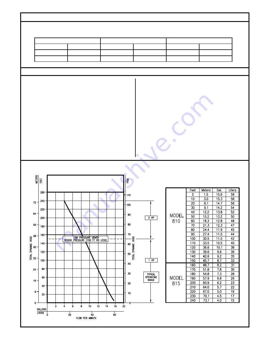
TOTAL DYNAMIC HEAD/FLOW
PER MINUTE
PUMP PERFORMANCE CURVE
MODEL 810/815