8
© Copyright 2020 Zoeller
®
Co. All rights reserved.
SERVICE CHECKLIST
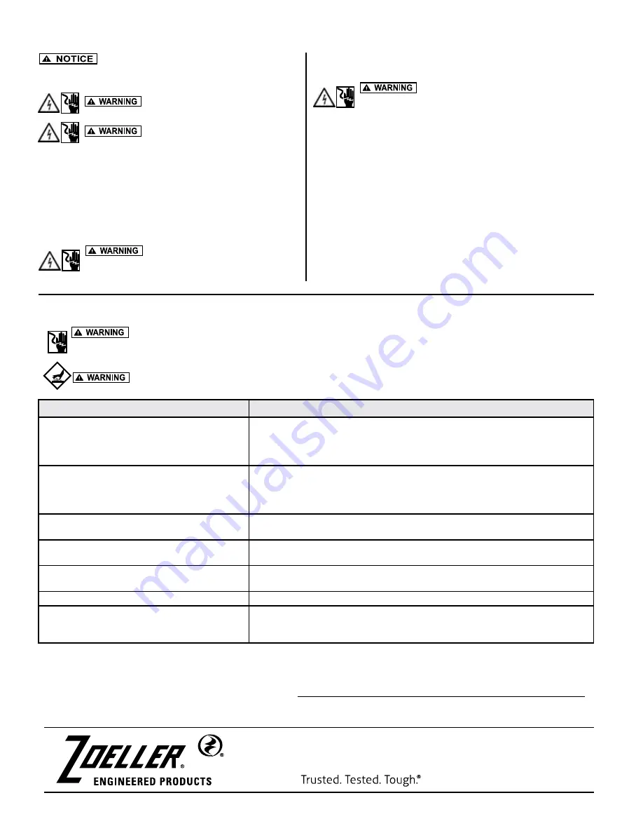
Electrical precautions. Before servicing a grinder pump, always shut off the main power circuit. Make sure you are wearing
insulated protective sole shoes and not standing in water. Under flooded conditions, contact your local electric company or a qualified
licensed electrician for disconnecting electrical service to the pump prior to removal.
Grinder pumps contain oil which becomes pressurized and hot under operating conditions. Allow 2-1/2 hours after shut
down before servicing pump.
MAIL TO:
P.O. BOX 16347 • Louisville, KY 40256-0347
SHIP TO:
3649 Cane Run Road • Louisville, KY 40211-1961
(502) 778-2731 • 1 (800) 928-PUMP •
FAX
(502) 774-3624
visit our web site:
zoellerengineered.com
GENERAL MAINTENANCE
Repair and service should be performed by a Zoeller
Authorized Service & Warranty Center or Customer Care Center only.
SAFETY PROCEDURES
For your protection, always disconnect
pump and panel from its power source before handling.
Never enter the basin until it has been
properly vented and tested. Any person entering a basin
should be wearing a harness with safety rope extending
to the surface so that they can be pulled out in case of asphyxiation.
Sewage water gives off methane and hydrogen sulfide gases, both of
which can be highly poisonous.
Installation and checking of electrical circuits and hardware should be
performed by a qualified electrician.
Pump is never to be lifted by power cord.
Unit must be cleaned and disinfected,
inside the pumping chamber and all exterior surfaces,
prior to servicing.
GENERAL SYSTEM INSPECTION
Before the system is placed into operation, it should be inspected by a
qualified technician.
Wiring and grounding must be in accordance
with the National Electrical Code and all applicable local
codes and ordinances.
LUBRICATION PROCEDURES
No lubrication is required.
If pumps are to be stored for more than six months, refer to short-term
storage procedure in the Operation section.
PREVENTIVE MAINTENANCE
Preventive maintenance is recommended to ensure a long service
life from the product. Provided is a suggested maintenance schedule.
Every year:
• Inspect basin, report any sighting of grease accumulation.
• Check for proper and unobstructed float operation.
• Listen for proper check valve operation.
Every 8 years or 2,000 hours of operation:
• Remove pump, inspect and service using a Zoeller rebuild kit.
• Flush and clean basin.
If the above checklist does not reveal the problem, consult the Product Support Department. Do not attempt to service or otherwise disassemble pump.
Service must be performed by a Zoeller Authorized Service Station. Go to https://www.zoellerengineered.com/en-us/where-to-buy/contact-us/service-locator
to find the Zoeller Authorized Service & Warranty Center or Customer Care Center in your area.
Condition
Common Causes
A. Pump will not start or run.
Blown panel or circuit breaker fuse, low voltage, thermal overload open, defective
capacitor circuit, cutter clogged, damaged hydraulic stator or rotor, float switch held
down or defective, incorrect wiring in control panel, water in cap assembly, check valve
not installed or malfunctioning.
B. Motor overheats and trips on overload.
Incorrect voltage, hydraulic rotor or cutter blocked, negative head (discharge lower
than intake of pump). Defective “off” float. Pump runs continuously at low water level.
Low oil level in motor shell. Pump running at shut-off head, check valve not installed or
malfunctioning.
C. Pump will not shut off.
Debris under float assembly, defective switch, incoming sewage exceeds capacity of
pump.
D. Pump operates but delivers little or no water.
Intake clogged with grease or sludge, damaged hydraulic stator or rotor, low or
incorrect voltage, clogged discharge line, operating near shut-off head.
E. Pump starts and stops too often.
Check valve stuck open or defective. Sump pit too small to handle incoming sewage.
Level control out of adjustment. Thermal overload tripping.
F. Large red flashing light comes on at control box.
High water in pit. Check pump for clogging, or overload trip.
G. Grease and solids accumulate in pit around pump. Break up solids and run pump with water running into the pit. Allow level to lower to the
pump intake. Continue until solids are cleared from the pit. Do not drain kitchen grease
down the sink.


