background image

4

© Copyright 2010 Zoeller Co. All rights reserved.

All installations must comply with all applicable electrical and plumbing codes, including, but not limited to, National Electrical Code, 
local, regional, and/or state plumbing codes, etc.

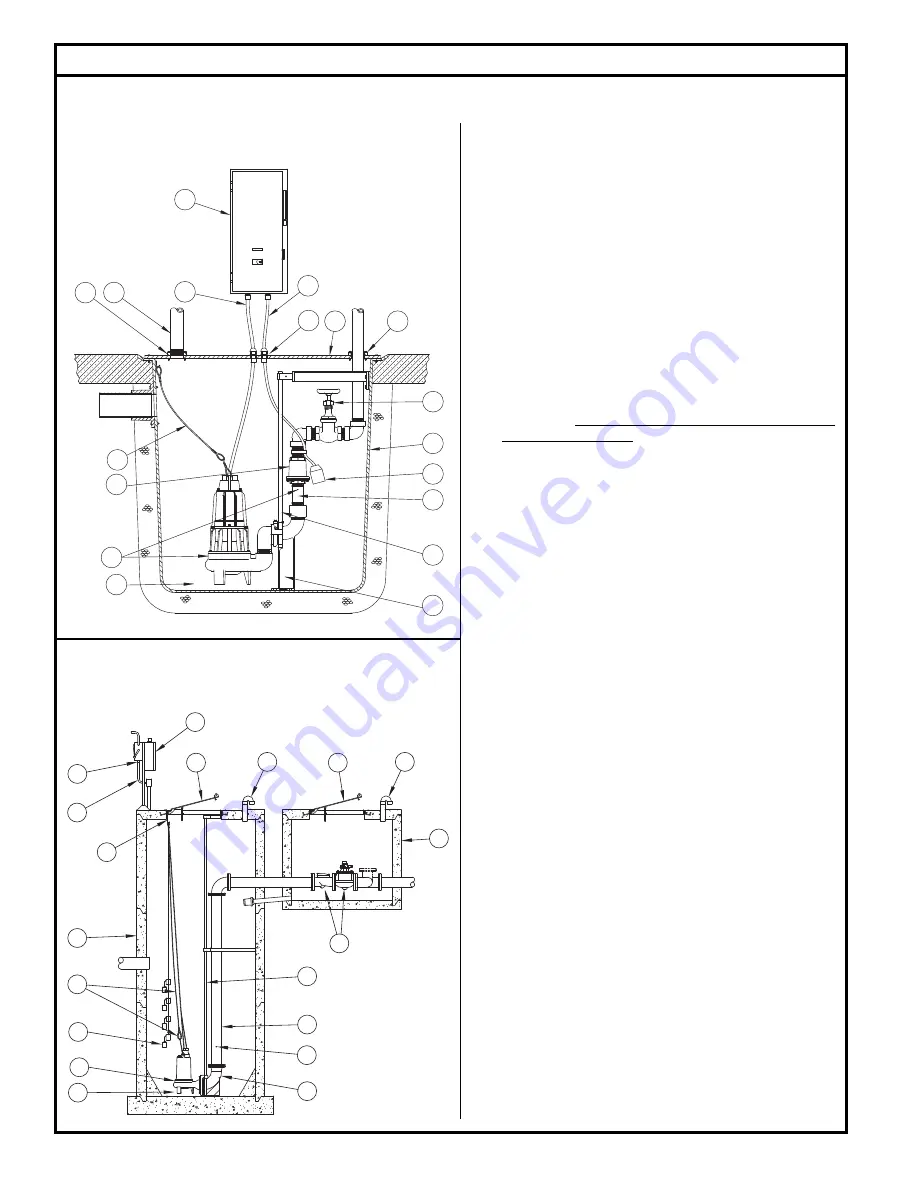
TYPICAL OUTDOOR CONCRETE BASIN WITH VALVE 

BOX AND HINGED ACCESS COVERS

TYPICAL INDOOR FIBERGLASS BASIN

Typical Sewage/Waste Pumping System Installation

  (1)   Electrical wiring and protection must be in accordance with the 

National Electrical Code, and any other applicable state and 

local electrical requirements.

  (2)   Install proper full fl ow check and shut-off valve.

  (3)   Install proper controls. (Outdoor panels require NEMA 3R or 

4X enclosure)

 (4) 


All 

installations 

require a basin cover to prevent debris from 

falling into the basin and to prevent accidental injury.

  (5)   Gas tight seals are required in all indoor sewage installations 

to contain gases and odors.

 (6) 


When check valve is installed, drill a 3/16” diameter hole in 

the discharge pipe below the check valve even with the top 

of the pump. NOTE: The hole must be below the basin cover 

and cleaned periodically. Water stream will be visible from this 

hole during pump run periods. Also a vent hole is drilled in the 

pump housing. Be sure that this hole is cleared during any 

servicing.

  (7)   Vent gases and odors to the atmosphere through vent pipe per 

Local and State codes.

  (8)   Secure power cord to avoid entanglement with variable level 

fl oat switch mechanism.

 (9) 


Do not reduce pump discharge pipe below 3” IPS size.

 (10)  Basin must be in accordance with all applicable codes


and 

specifi cations. Basin must be sized to allow a minimum 3 

minute lapse time between starts.

  (11)   Pump must be level and the tethered variable level fl oat switch 

must be free and not hang up on pump or pit peculiarities.

 (12) If a rail system is used, discharge elbow must be fi rmly anchored 

to the bottom of basin. In fi berglass basin, the bottom will need 

to be reinforced if the discharge elbow is used.

 (13) If a rail system is used, the guide rails are ¾” schedule 40 pipe 

for threaded vertical discharge units and 2” schedule 40 pipe 

for fl anged horizontal discharge units. Brass, stainless steel or 

galvanized steel is recommended.

  (14)   Install ring and cable for lifting pump from pit.

  (15)   Basin must be clean and free of debris after installation.

  (16)  Cords must be properly sealed to prevent moisture and gases 

from entering the control panel. 

3

8

7

5

16

1

14

6

13

12

11

10

2

2

9

5

4

15

ZEPA0466

ZEPA0071

7

4

4

7

3

16

1

10

6

12

9

6

13

2

10

14

15

8

11

Содержание 600 Series

Страница 1: ...mp but also save time and money during installation Reference FM1799 for repair manual on 600 Series Pumps Should further assistance be necessary please call our Technical Service Department at 1 800 928 PUMP 7867 Table of Contents Safety Instructions 1 Limited Warranty 2 Performance Data 2 Preinstallation Information 3 Electrical Data 3 Typical Dewatering Installation 4 Typical Sewage Installatio...

Страница 2: ...ranty for any material or product that has been disassembled without prior approval of Manufacturer subjected to misuse misapplication neglect alteration accident or act of God that has not been installed operated or maintained in accordance with Manufacturer s installation instructions that has been exposed to outside sub stances including but not limited to the following sand gravel cement mud t...

Страница 3: ...tallation a vent hole approx 3 16 must be drilled in the discharge pipe below the check valve and pit cover to purge the unit of trapped air Water stream will be visible from this hole during pump run periods This vent hole should be checkedperiodicallyforcloggingandcleanedasnecessary Trappedairiscaused by agitation and or a dry basin 4 Water hammer creates momentary high pressure surges These sur...

Страница 4: ...ump run periods Also a vent hole is drilled in the pump housing Be sure that this hole is cleared during any servicing 7 Vent gases and odors to the atmosphere through vent pipe per Local and State codes 8 Secure power cord to avoid entanglement with variable level float switch mechanism 9 Do not reduce pump discharge pipe below 3 IPS size 10 Basin must be in accordance with all applicable codes a...

Страница 5: ...ted capacitors and starting relays Your control panel should have provisions for mounting these starting components 2 All pumps require overload protection in panel Use with approved motor control that matches motor input in full load amperes with overload element s selected or adjusted in accordance with control instructions 3 Hazardous Location pumps require panels that offer intrinsically safe ...

Страница 6: ...or seal in plastic bag the terminal ends of wire leads Single Phase Installation All single phase models require start capacitor run capacitor and relay in the circuit to start and operate properly These components can be pur chased separately or prewired in Zoeller control panel For components purchased separately used the diagram for installation and hookup Single phase models are nonautomatic T...

Страница 7: ...has been properly vented and tested Any person entering a basin should be wearing a harness with safety rope extending to the surface so that they can be pulled out incaseofasphyxiation Sewagewatergivesoffmethaneandhydrogen sulfide gases both of which can be highly poisonous Installation and checking of electrical circuits and hardware should be performed by a qualified electrician Pump is never t...

Страница 8: ...fective Pit too small D Pump will not shut off Debris under float switch Float travel obstructed Defective or damaged float switch Magnetic starter contacts shorted Air lock check vent hole E Pump operates but delivers little or no water Check for plugged Pump housing discharge pipe or sticking check valve Vent hole clogged or not drilled Discharge head exceeds pumps capacity Low or incorrect volt...

Отзывы: