


ZMC412 Motion Controller User Manual V1.5
→
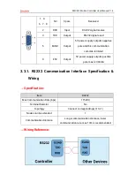
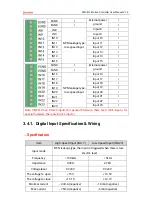
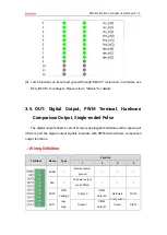
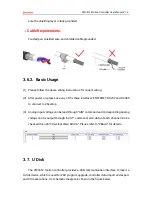
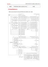
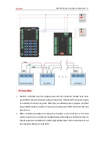
Interface Definition
Interface
Pin
Signal
Description
1
EGND
Negative pole of IO 24V power
2
IN24-
35/ALM
Digital input, it is recommended to
do drive alarm
3
OUT12-
13ENABLE
Digital output, it is recommended
to do drive enable
4
EA-
Encoder differential input signal A-
5
EB-
Encoder differential input signal B-
6
EZ-
Encoder differential input signal Z-
7
+5V
Positive pole of 5V power of
pulse/encoder signal
8
Reserved
Reserved
9
DIR+
Servo or step direction
10
GND
Negative pole of 5V power of
pulse/encoder signal
11
PUL-
Servo or step pulse output -
12
Reserved
Reserved
13
GND
Negative pole of 5V power of
pulse/encoder signal
14
OVCC
Positive pole of IO 24V power
15
Reserved
Reserved
16
Reserved
Reserved
17
EA+
Encoder differential input signal A+
18
EB+
Encoder differential input signal B+
19
EZ+
Encoder differential input signal Z+
20
GND
Negative pole of 5V power of
pulse/encoder signal
21
GND
22
DIR-
Servo or step direction output -
23
PUL+
Servo or step pulse
24
GND
Negative pole of 5V power of
pulse/encoder signal
25
Reserved
Reserved
26
Reserved
Reserved
Содержание ZMC412
Страница 1: ......