ZLG CANSwitch-AF2S2 Скачать руководство пользователя страница 77

CANSwitch-AF2S2 

High-Performance Dual-CAN to Fiber Switch User Manual 


©2021 Guangzhou ZLG Electronics Technology Co.,Ltd.


73 

User Manual


5.5  Saving Restored Settings 

To  help  you  modify  the  configurations  of  the  CANSwitch-AF2S2  device  in  batches, 

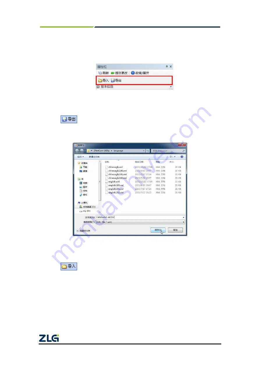
the  ZNetCom  software  allows  you  to  import/export  configurations.  The  Import/Export 

function button is located on the property column, as shown in Figure 5.14. 


Figure 5.14 Device configurations import/export


5.5.1  Saving Settings 

Click 

. In the "Save As" dialog box (as shown in Figure 5.15), select the save 

path,  enter  the  file  name,  and  click  [Save].  Device  configurations  will  be  saved  in  XML 

format. 


Figure 5.15 Saving device configurations


5.5.2  Restoring Settings 

Click 

. In the "Open" dialog box (as shown in Figure 5.16), select the saved 

device configuration file, and click the [Open] button. The ZNetCom software imports the 

settings saved in the file. 

Содержание CANSwitch-AF2S2

Страница 1: ...tegory Contents Keywords Dual CAN dual optical hardware switch converter hub Description CANSwitch AF2S2 is a high performance dual channel CAN to fiber switch based on ZLG Electronics advanced CAN bu...

Страница 2: ...anual Revision History Version Date Description V1 00 December 27 2015 Created V1 01 August 11 2017 Changed the company name and sales network information V1 02 March 14 2019 Updated the document head...

Страница 3: ...button and function switch 7 2 5 Fiber interface 8 2 6 CAN port 8 2 7 LED indicator 9 3 Quick use in hub mode Hub mode 10 3 1 Device configuration method 10 3 2 System block diagram 10 3 3 Configure...

Страница 4: ...gram 43 4 5 2 Configuring the CANSwitch AF2S2 device 45 4 5 3 TCP UDP software operation 45 4 5 4 CANTest software operation 47 4 5 5 Test Result 49 5 ZNetCom software configuration 53 5 1 Install con...

Страница 5: ...also has the characteristics of not radiating energy non conducting and non inductive Moreover there is no influence of crosstalk and mutual interference of optical signals in the optical cable it ha...

Страница 6: ...C metal 1 1 mm Specifically designed for industrial and military environments 1 1 2 Perfect Functions In Hub mode Cascading is supported A maximum of 32 levels can be cascaded Each CAN port can be set...

Страница 7: ...host computer communication software follows the standard SOCKET rules Each CAN port can be set to a different baud rate Two way transparent transmission of CAN data and optical fiber data for the fo...

Страница 8: ...configuration software version 2 95 or later CANtest test tool TCP UDP test tool Configuration method Windows configuration software ZNetCom 1 2 6 EMC Characteristics Electrostatic Discharge Immunity...

Страница 9: ...y Co Ltd 5 User Manual 1 3 Mechanical Dimensions To install CANSwitch AF2S2 see the appearance and mechanical dimensions unit mm provided in Figure 1 3 The figure specifies the length width height and...

Страница 10: ...re Interfaces This chapter describes the hardware interfaces of CANSwitch AF2S2 2 1 Appearance Drawing Figure 2 1 shows the front appearance of the product Figure 2 2 and Figure 2 3 show the side appe...

Страница 11: ...rface As shown in Figure 2 5 this interface is specially used to configure the CANSwitch AF2S2 device Figure 2 5 Configuring ports 2 4 Reset Button Default Restoration Button and Function Switch As sh...

Страница 12: ...the Active indicator flashes Figure 2 7 Optical fiber interface and indicators 2 6 CAN Port The CANSwitch AF2S2 device has two CAN ports Figure 2 8 shows its appearance It has two indicators CAN0 and...

Страница 13: ...tem running indicator When the device is not ready to start or fails the red indicator is steady on when it is running properly the green indicator flashes Fiber0 Fiber1 Active LAN working indicator f...

Страница 14: ...e as shown in Figure 3 1 The device can be configured as long as the dedicated RS232 configuration port is connected to the PC Figure 3 1 Dedicated configuration port 3 2 System Block Diagram This doc...

Страница 15: ...User Manual Figure 3 2 System block diagram in Hub mode 3 3 Configuring the Device Search devices The CANSwitch supports searching by serial port When searching by serial port the COM port should be...

Страница 16: ...ing Select 3 as the number of networking devices a maximum of 32 devices are supported for cascading this device is the first networking device so select 1 as the device number The baud rate should be...

Страница 17: ...pported for cascading this device is the second networking device so select 2 as the device number Be sure to submit the configuration modifications The default password is 88888 The baud rate should...

Страница 18: ...e 3 6 Configuration of the third CANSwitch Be sure to submit the configuration modifications The default password is 88888 A total of three devices are used for networking Select 3 as the number of ne...

Страница 19: ...Configure a 120 ohm terminal resistance Then connect the USBCAN interface card with the PC by using a USB cable Finally connect power to the USBCAN interface card and the CANSwitch AF2S2 device Run t...

Страница 20: ...f the device is connected properly there will be no prompt If the connection is abnormal an error message appears Figure 3 10 Starting USBCAN E U successfully On the tab page of any CANtest software c...

Страница 21: ...xth CAN buses receive data and the third and fourth CAN buses do not receive data which conforms to the configuration of the first CANSwitch AF2S2 See Figure 3 12 Figure 3 12 First CAN bus sending dat...

Страница 22: ...d data and all other CAN buses can receive data which conforms with the configuration of the second CANSwitch AF2S2 See Figure 3 14 Figure 3 14 Third and fourth CAN buses sending data The fifth and si...

Страница 23: ...CANSwitch AF2S2 High Performance Dual CAN to Fiber Switch User Manual 2021 Guangzhou ZLG Electronics Technology Co Ltd 19 User Manual Figure 3 15 Fifth and sixth CAN buses sending data...

Страница 24: ...he ZNetCom software The CANSwitch AF2S2 device supports two IP address acquisition methods static acquisition and dynamic acquisition Static acquisition indicates that the device uses the IP address s...

Страница 25: ...ppears where you can obtain the IP address of the device Figure 4 3 Searching for devices by using the ZNetCom software 4 2 3 PC and Device Network Segment Detection Before using the PC to communicate...

Страница 26: ...If you are using Windows 2000 XP 7 8 10 there are two methods One is to add the local IP address and the other is to change the local IP address 4 2 4 Adding the IP Address of the Machine Use Windows7...

Страница 27: ...r Manual Figure 4 5 Local connection properties 1 Select Internet Protocol Version 4 TCP Ipv4 and click Properties as shown in Figure 4 6 Figure 4 6 Local area connection properties 2 The General page...

Страница 28: ...ectronics Technology Co Ltd 24 User Manual Figure 4 7 TCP Ipv4 Properties Click the Add button as shown in Figure 4 8 Figure 4 8 TCP IP settings Enter the IP address and subnet mask in this window The...

Страница 29: ...yed dialog box select Internet Protocol Version 4 TCP Ipv4 and click Properties The page shown in Figure 4 10 is displayed Select Use the following IP address and enter the IP address 192 168 0 22 the...

Страница 30: ...ch User Manual 2021 Guangzhou ZLG Electronics Technology Co Ltd 26 User Manual Figure 4 11 Communication in TCP Sever mode Tip In this mode the client connects to the CANSwitch AF2S2 device over the w...

Страница 31: ...ware and click to create a connection as shown in Figure 4 14 Figure 4 12 Configuration in TCP Sever mode Be sure to submit the configuration modifications The default password is 88888 The IP address...

Страница 32: ...Technology Co Ltd 28 User Manual Figure 4 14 Open the TCP UDP test tool Select TCP mode in Type enter the IP address and the working port number of CANSwitch AF2S2 and click Create See Figure 4 15 Fi...

Страница 33: ...ber Switch User Manual 2021 Guangzhou ZLG Electronics Technology Co Ltd 29 User Manual Figure 4 16 Opening a connection When the triangle below the client mode turns green the connection is successful...

Страница 34: ...Software Operation Double click the CANTest software icon to run the software as shown in Figure 4 18 Figure 4 18 CANTest software Choose the correct device Select USBCAN E U here as shown in Figure...

Страница 35: ...1 Starting the device For details about how to use the CANTest software see the ZLG Electronics CAN Test Software and Interface Function User Manual 4 3 5 Test Result Send a CAN frame whose ID is 0000...

Страница 36: ...tool to receive data Because the frame ID filter is set and ID00000000 is no longer in the receiving range no data is received as shown in Figure 4 23 Figure 4 23 PC receiving data 1 The CAN frame wit...

Страница 37: ...ology Co Ltd 33 User Manual Figure 4 24 USBCAN sending data 2 The device has received the data as shown in Figure 4 25 For the format of the received data see Appendix A Figure 4 25 PC receiving data...

Страница 38: ...filter only filters the frame ID sent from the CAN port to the optical fiber and the frame ID sent from the optical fiber to the CAN port is not filtered both frames of data USBCAN can be received pro...

Страница 39: ...wo way data communication can be carried out Figure 4 28 shows the communication establishment process Figure 4 28 Communication in TCP Client mode Tip In this mode the TCP server IP address is determ...

Страница 40: ...rt and click OK See Figure 4 31 Figure 4 29 Configuration in TCP Client mode Be sure to submit the configuration modifications The default password is 88888 The IP address configuration should be corr...

Страница 41: ...zhou ZLG Electronics Technology Co Ltd 37 User Manual Figure 4 31 Creating a connection Click Start Server to start the service See Figure 4 32 Figure 4 32 Opening a connection When the triangle under...

Страница 42: ...ectronics Technology Co Ltd 38 User Manual Figure 4 33 Connection created 4 4 4 CANTest Software Operation Double click the CANTest software icon to run the software as shown in Figure 4 34 Figure 4 3...

Страница 43: ...2021 Guangzhou ZLG Electronics Technology Co Ltd 39 User Manual Figure 4 35 Selecting a device Select a baud rate click OK and start the CAN as shown in Figure 4 36 Figure 4 36 Opening the device Aft...

Страница 44: ...LG Electronics CAN Test Software and Interface Function User Manual 4 4 5 Test Result Send a CAN frame whose ID is 00000000 and data is 0001020304050607 by using the CANTest software over USBCAN Becau...

Страница 45: ...l ID00000000 is no longer in the receiving range no data is received as shown in Figure 4 39 Figure 4 39 PC receiving data 1 The CAN frame with ID 00000011 and data 0001020304050607 is sent and the ID...

Страница 46: ...1 For the format of the received data see Figure 4 41 PC receiving data 2 Use the TCP UDP test tool to send CAN frames as shown in Figure 4 42 For the data format see Appendix A Figure 4 42 PC sending...

Страница 47: ...ectly Therefore in the scenarios with high reliability requirements the upper layer communication protocol must be used to ensure that the data is correct however because UDP is a simple communication...

Страница 48: ...ogy Co Ltd 44 User Manual Tip In this mode the CANSwitch AF2S2 uses working port see Table 5 2 to receive UDP packets sent by user equipment the data received by the CAN port of the CANSwitch AF2S2 de...

Страница 49: ...software and click to create a connection as shown in Figure 4 47 Figure 4 45 Configuration in UDP mode Be sure to submit the configuration modifications The default password is 88888 The IP address c...

Страница 50: ...gy Co Ltd 46 User Manual Figure 4 47 Opening the TCP UDP test tool Select UDP mode in Type enter the IP address and the working port number of CANSwitch AF2S2 and local port and click Create See Figur...

Страница 51: ...nology Co Ltd 47 User Manual Figure 4 49 Opening a connection When the triangle below the client mode turns green the connection is successful See Figure 4 50 Figure 4 50 Connection created 4 5 4 CANT...

Страница 52: ...r Manual Figure 4 51 CANTest software Choose the correct device Select USBCAN E U here as shown in Figure 4 52 Figure 4 52 Selecting a device Select the correct baud rate click OK and start the CAN as...

Страница 53: ...ils about how to use the CANTest software see the ZLG Electronics CAN Test Software and Interface Function User Manual 4 5 5 Test Result Send a CAN frame whose ID is 00000000 and data is 0001020304050...

Страница 54: ...er Manual Figure 4 24 PC receiving data 1 Send the CAN frame whose ID is 00000022 and data is 0001020304050607 The peer device can receive the data correctly as shown in Figure 4 57 Figure 4 57 USBCAN...

Страница 55: ...y Co Ltd 51 User Manual Figure 4 58 PC receiving data 2 Use the TCP UDP test tool to send CAN frames as shown in Figure 4 59 For the data format see Appendix A Figure 4 59 PC sending data 1 Since ther...

Страница 56: ...CANSwitch AF2S2 High Performance Dual CAN to Fiber Switch User Manual 2021 Guangzhou ZLG Electronics Technology Co Ltd 52 User Manual Figure 4 60 USBCAN receiving data 1...

Страница 57: ...re 5 1 Installing the Configuration Software Insert the CD ROM into the CD ROM drive and open the CD ROM you can download the latest ZnetCom software at http www zlg cn Double click the ZNetComSetup e...

Страница 58: ...Selecting an installation path Click Install to copy the files to the installation path If the dialog box shown in Figure 5 4 appears select Yes Figure 5 4 Installing the runtime library After the in...

Страница 59: ...onfigurations Before obtaining the configuration information check whether the RS232 configuration serial port has been connected to the computer or the CANSwitch AF2S2 device and the PC network card...

Страница 60: ...u use the LAN port to connect to the PC choose optical fiber if you use the RS232 configuration serial port to connect to the PC choose the serial port If you choose the serial port you should select...

Страница 61: ...ter the search is completed the searched devices appear in the device list of the ZNetCom software as shown in Figure 5 9 Figure 5 9 Obtaining CANSwitch AF2S2 device configuration properties Double cl...

Страница 62: ...hnology Co Ltd 58 User Manual Figure 5 10 Obtaining configuration data When the Get Device Information dialog box disappears you can view the CANSwitch AF2S2 device configurations as shown in Figure 5...

Страница 63: ...AF2S2 High Performance Dual CAN to Fiber Switch User Manual 2021 Guangzhou ZLG Electronics Technology Co Ltd 59 User Manual Figure 5 12 CANSwitch AF2S2 device configuration information converter Conve...

Страница 64: ...F2S2 device configurations by using the ZNetCom software the device configuration password the default value is 88888 is required After you modify the device configurations in the property column ente...

Страница 65: ...AF2S2 devices on the same network Password operation Current password 88888 Before changing other items you must enter the correct password The password contains a maximum of 10 characters including...

Страница 66: ...works in listening mode and does not respond Self test The CAN port works in self transmitting and self receiving mode This is used to check whether if it can properly and whether it is damaged CAN_A...

Страница 67: ...eter values of CAN1 are exactly the same the meaning of each parameter is the same as that of each parameter of CAN0 5 4 2 Configuration in Converter Mode Converter Mode Table 5 2 describes the device...

Страница 68: ...cannot be changed Used to confirm the new password It must be the same as New Password IP address informati on operation Device IP address 192 168 0 178 X X X 0 or X X X 255 cannot be filled An IP add...

Страница 69: ...ect Dynamic acquisition Static acquisition means that you directly enters the IP address Subnet mask and Gateway Dynamic acquisition means that the CANSwitch AF2S2 module uses the DHCP protocol to obt...

Страница 70: ...and port When the device works in UDP mode by setting the destination IP address the device can communicate with multiple network devices with different IP addresses at the same time Whether the port...

Страница 71: ...connection is established If no data is received before the timeout period expires the TCP connection is disconnected 0 indicates it will not be disconnected all the time Heartbeat time 10 ms 200 The...

Страница 72: ...xceeds the packet time interval the received data is also encapsulated into an optical fiber packet and sent If the number of packetized frames is set to 1 it means no packetization Each CAN frame is...

Страница 73: ...nabling After enabling enter the upper and lower limits of the standard frame ID and the upper and lower limits of the extended frame ID to be received in the following four items Only the frame ID se...

Страница 74: ...ither the client controls the transmission speed of the optical fiber to match the transmission speed of the CAN port or the buffer is changed to a smaller size and the frame is dropped appropriately...

Страница 75: ...168 1 x If the subnet mask is 255 255 255 0 the IP 192 168 1 255 is a broadcast address and cannot be used to represent a host But if the subnet mask is 255 255 0 0 192 168 1 255 is an illegitimate d...

Страница 76: ...for shielding To enable it set the number of TCP connections Start addresses 2 6 0 0 0 0 The function is the same as the starting address 1 To enable it set the number of TCP connections End addresse...

Страница 77: ...is located on the property column as shown in Figure 5 14 Figure 5 14 Device configurations import export 5 5 1 Saving Settings Click In the Save As dialog box as shown in Figure 5 15 select the save...

Страница 78: ...re the PC and the CANSwitch AF2S2 device must be on the same network segment refer to 4 2 PC and device network segment detection The firmware upgrade procedure is as follows 1 In the device list colu...

Страница 79: ...ology Co Ltd 75 User Manual Figure 5 18 Firmware upgrade 3 Click The device starts firmware upgrade as shown in Figure 5 19 Figure 5 19 Firmware upgrade in progress 4 After about 1 minute the firmware...

Страница 80: ...User Manual 2021 Guangzhou ZLG Electronics Technology Co Ltd 76 User Manual Figure 5 20 Firmware upgraded If the upgrade fails due to an accident such as power failure and network cable disconnection...

Страница 81: ...cs will try to present detailed and accurate product information in this manual However due to the effectiveness of this manual within a particular period of time ZLG Electronics does not guarantee th...

Страница 82: ...port data conversion format CAN CAN CAN CAN CAN UDP CAN 40 1 CAN 1 CAN 13 1 CAN FF RTR D3 D2 D1 D0 Bit7 Bit0 FF 1 0 RTR 1 0 0 1 D3 D0 CAN ID 4 11 29 12h 34h 56h 78h ID 0x12345678 00h 00h 03h FFh ID 0...

Страница 83: ...contained in each UDP frame cannot be greater than 50 frames It is recommended that the sending speed of UDP frames should not exceed 400 packets per second There is another condition If the user has...

Страница 84: ...er overflowed 0 0 5s 02h Fiber receive buffer about to overflow 0 2s 03h Fiber receive buffer overflowed 0 0 5s 04h The CAN controller sends an error alarm send error counter 96 Number of occurrences...

Страница 85: ...al CAN to Fiber Switch User Manual 2021 Guangzhou ZLG Electronics Technology Co Ltd 81 User Manual occurrences 0Bh CAN controller bus error as long as there is an error Number of occurrences 2s 0Ch Ot...

Страница 86: ...ser Manual 2021 Guangzhou ZLG Electronics Technology Co Ltd 82 User Manual Dreams come true with professionalism and dedication Guangzhou ZLG Electronics Co Ltd For more details please visit www zlg c...

Отзывы: