CANFDNET-200U
High-Performance Dual-Channel Ethernet to CAN (FD) Converter User Manual
©2021 Guangzhou ZLG Electronics Co., Ltd.
7
User Manual
Send
4,000 frames/s
CAN1
Receive
10,000 frames/s
Send
6,000 frames/s
Table 4.5 Pin definitions
Type
Schematic Diagram
Pin definitions
Table 4.6 Signal definition
Function Interface
Signal Definition
Signal Description
Pin Number
CAN0~CAN1
CAN_L
CAN data transceiving differential inverted signal
2
CAN_GND
CAN isolated ground
3, 6
CAN_H
CAN data sending and receiving differential positive phase signal
7
CAN_FG
Shielding ground
5
NC
Not connected
1, 4, 8, 9
Table 4.7 CAN-Bus interface specifications
Item
Minimum
Typical Value
Maximum
Unit
Communication baud rate
40K
5M
bps
Number of nodes
110
pcs
Dominant level (logic 0)
CANH
2.75
3.5
4.5
V
CANL
0.5
1.5
2
Recessive level (logic 1)
CANH
2
2.5
3
CANL
2
2.5
3
Differential level
Dominant (logic 0)
1.2
2
3.1
Recessive (logic 1)
-0.5
0
0.05
Maximum withstand voltage of the
bus pin
-18
18
Instantaneous voltage of the bus
-100
+100
Isolation voltage (DC)
3500
V
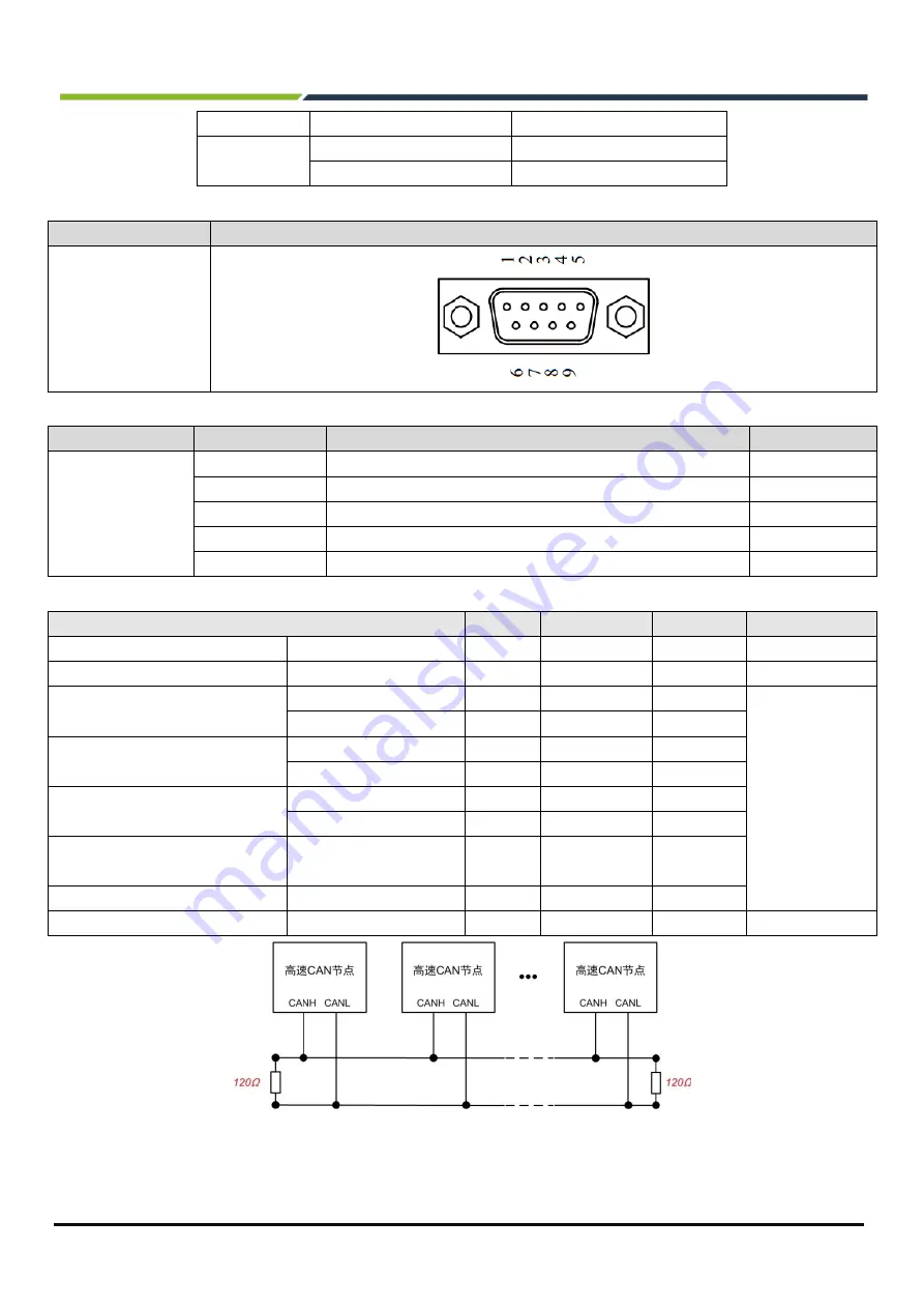
Figure 4.2 Typical high-speed CAN network connection
Balanced transmission is adopted for the CAN bus. According to ISO11898-2: In the high-speed CAN, a 120


