CANFDNET-400U
High-Performance Four-Channel CANFD Bus-to-Ethernet Converter User Manual
©2021 Guangzhou ZLG Electronics Technology Co.,Ltd.
9
User Manual
2.6 CAN Communication Interface
The commonly used electrical connectors for CAN-bus communication interface are:
DB9 socket, OPEN5 socket, OPEN3 socket, etc. The CANET-8E-U interface card
integrates 1 to 8 CAN channels, which can be used to connect CAN-bus network or
devices equipped with CAN-bus interface. The CAN-bus channel of CANET-8E-U adopts
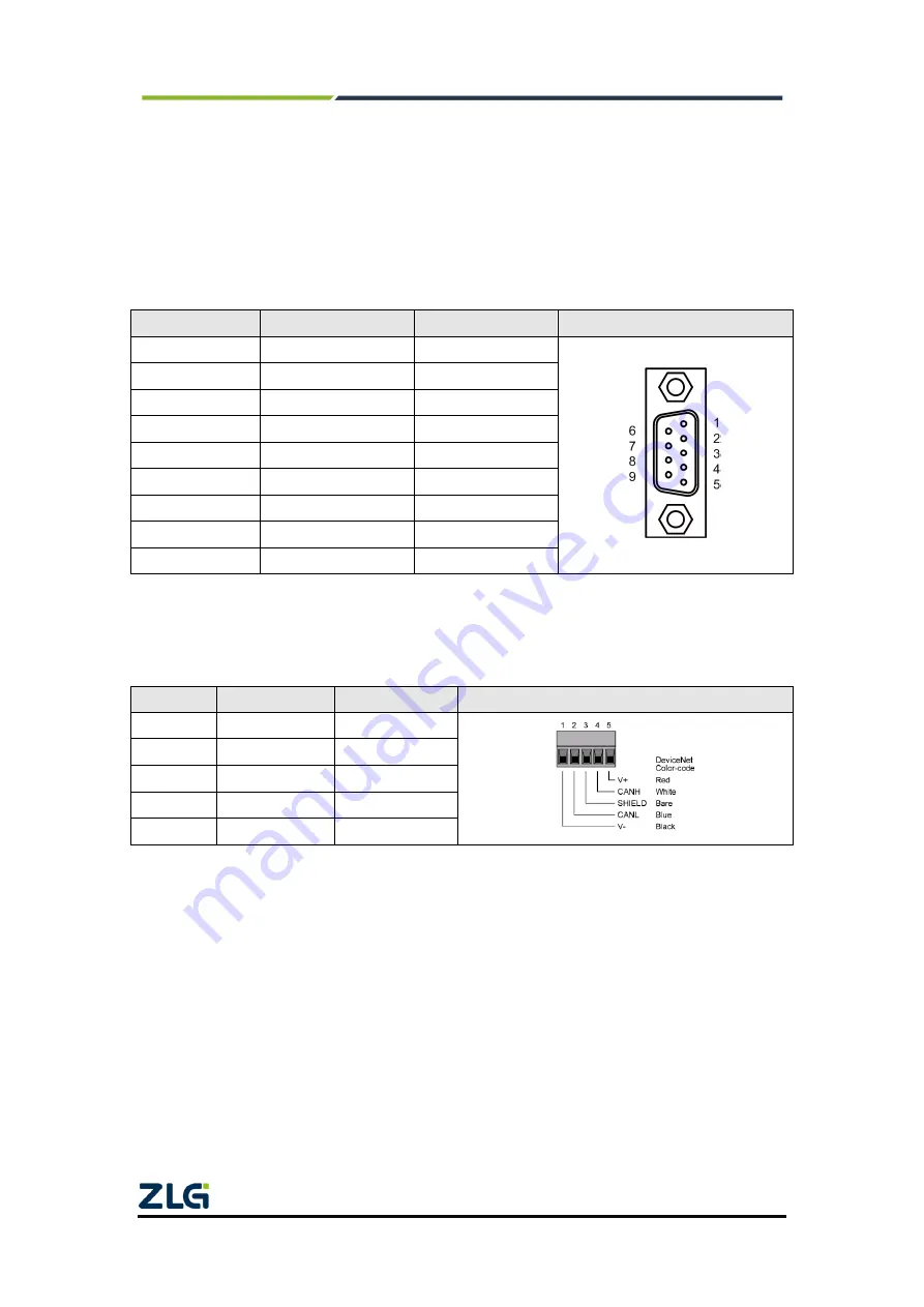
the standard male DB9 socket. Table 2.3 lists the DB9 pin definitions.
Table 2.3 DB9 pin socket pin signal definitions of CANET-8E-U
Pin
Signal
Description
Function
1
NC
Unused
2
CAN_L
CAN_L signal cable
3
CGND
Reference ground
4
NC
Unused
5
CAN_SHIELD
Shielded cable
6
CGND
Reference ground
7
CAN_H
CAN_H signal cable
8
NC
Unused
9
NC
Unused
In some applications, some CAN-bus interfaces are OPEN-5 interfaces, and
CANET-8E-U comes standard with eight DB9-to-OPEN5 connectors. Table 2.4 describes
the signal definitions for the OPEN5 socket.
Table 2.4 Definition of accessories DB9 to OPEN5 signal
Pin
Signal
Description
Picture
1
V-
Reference
ground
2
CAN_L
CAN_L signal
cable
3
CAN_SHIELD
Shielded cable
4
CAN_H
CAN_H signal
cable
5
V+
Unused


