background image

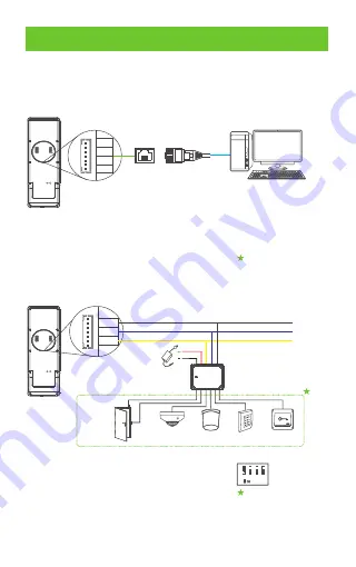
Equipment Connection

Connect the device and computer software over an Ethernet cable.
An example is shown below:

PC

8

7

6

5

4

3

2

1

TX+

TX-

RX+

RX-

Default IP address: 192.168.1.201
Subnet mask: 255.255.255.0

IP address: 192.168.1.130
Subnet mask: 255.255.255.0

Note:

1.  In LAN, IP addresses of the server (PC) and the device must be in

the same network segment.

2.  It only supports Horus E1-RFID and Horus E1-FP.

1 Ethernet Connection

.

2 RS485 Connection and Extend DM10

.

GND

485+

485-

DC12V

GND
485A
485B

6

DM10

Note:

1.  DM10 needs to be powered separately.
2. The address of the DM10 DIP switch defaults to                  .
3.  It only supports Horus E1-RFID and Horus E1-FP.
4.  Not all devices support all function: Door Sensor, Lock, Smoke Detector,

Alarm, Reader and Exit Button, it's based the Horus rmware, please
con rm with technical support before the sales.

Lock

Exit Button

Door Sensor

Reader

Alarm

Smoke

detector

1

2

3

4

Содержание Horus

Страница 1: ...Quick Start Guide HORUS Version 1 2 Date November 2019 ...

Страница 2: ...ower Reset button 1 Fixing hole Microphone Side Flash Type C power interface SIM Card port Front Camera 5 inch Screen Infrared sensors Rear Bottom Device Overview Near infrared Type C power interface OTG debugging interface ...

Страница 3: ...ction 2 Not all the devices have the function with the real product prevails Fingerprint Sensor ID MF Card read area Front TCP IP and RS485 extend port Horus E1 RFID Horus E1 FP has the port Rear GND 485 485 TX TX RX RX RS485 Ethernet Port Connection Bottom Bottom Reset Button Type C power interface ...

Страница 4: ... Outdoor Direct Sunlight through window Indirect Sunlight through window Too close to light source 2 Installation Steps Step 1 Put the mounting template sticker onto the wall and drill holes according to the mounting paper Step 2 Fix the back plate onto the wall using wall mounting screws Step 3 Insert the device into back plate Step 4 Use security screw to fasten the device to back plate 1 1 55m ...

Страница 5: ...se security screw to fasten 2 And u the device to back plate 1 2 put it on the table c Mounting on the glass door Step 1 Attach the double sided tape to the back panel Then attach the back plate to the glass door Step Use security screw to fasten the 2 Fix the device to the back plate device to back plate 1 2 Double sided tape 2 ...

Страница 6: ...t adaptor board with two screw and nuts Step 3 Fix the adaptor board onto the 86 box or Single Gang box using four wall mounting screws Step 4 Insert the device into back plate Step 5 Use security screw to fasten the device to back plate Wall Adaptor board Back plate 1 2 3 4 5 Power Connection Recommended power supply 12V 10 at least 2000mA Please use the supplied Type C power plug 5 ...

Страница 7: ...segment 2 It only supports Horus E1 RFID and Horus E1 FP 1 Ethernet Connection 2 RS485 Connection and Extend DM10 GND 485 485 DC12V GND 485A 485B 6 DM10 Note 1 DM10 needs to be powered separately 2 The address of the DM10 DIP switch defaults to 3 It only supports Horus E1 RFID and Horus E1 FP 4 Not all devices support all function Door Sensor Lock Smoke Detector Alarm Reader and Exit Button it s b...

Страница 8: ...ress 0 0 0 0 Comm connection settings ATT Events User Mgt Access Settings Attendanc e Search Data Mgt Cloud service settings Server Server type Enable domain name Server address Server port Enable proxy server Open HTTPS ADMS 0 0 0 0 8081 Restart manually to complete setup Network settings Date and time ATT parameters Cloud service settings Serial port setting Display settings Sound settings Biome...

Страница 9: ...egistration 1 Register on the device Click User Mgt to register new user Enter user name ID register face fingerprint badge number fingerprint and ID card are optional and password Note 1 It s recommended to register multiple administrators 2 It s recommend enroll user s face in 0 5 0 75m distance it s good for 1 5 1 8m height person 0 5 0 7m 1 5m 1 5m 1 8m L Attendanc e Search User Management ATT...

Страница 10: ...ork connection or the server is abnormal Please check the network cable and network connection 3 Register on the phone Once BioTime 8 0 software installation users could enroll face via broswer application on their own mobile phone Register visible light comparison photos to verify and punch on the visible light device a Choose Personnel Employee Bio photo QR Code to access the QR Code getting int...

Страница 11: ...ace verification interface automatically once it detect bright of environment change The verification resultshowsasrightimage Verify successfully 2018 08 03 20 44 43 Tom 1 Verification is successful View records View records on the software Click Attendance Report on the software to view the records 10 ...

Отзывы: