26
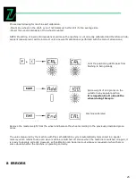
Various abnormal conditions can arise during machine operation. If detected by microprocessor, they appear on
the display the ERROR number:
ERROR MEANING
1 No rotation signal. Could be caused by faulty position transducer, or something preventing the wheel
froturning.
2. During the measurement spins, wheel speed had dropped to below minimum 60 r.p.m. Repeat the spin
3. Error in mathematical calculations; most probably caused by too high wheel unbalance.
4. Rotation in opposite direction.
5. Guard open before start of the spin.
7 Fault in memory of the self-calibration values. Repeat the self-calibration.
8. Error during self-calibration. Could be due to the second spin made without adding reference weight, or else
by a break in the transducer cable. .
INCONSISTENT UNBALANCE READINGS
Sometimes after balancing a wheel and removing it from the balancing machine, then again mounting it on the
balancing machine, it is found that the wheel is not balanced.
This does not depend on incorrect indication of the machine, but only on a faulty mounting of the wheel on the
adapter, i.e. in the two mountings, the wheel has assumed a different position with respect to the balancing ma-
chine shaft center line.
If the wheel is mounted on the adapter with screw, it could be possible that the screws have not be correctly
tightened- they should be tightened one by one crosswise or else (as often happened) holes have been drilled on
the wheel with too wide tolerance.
Small errors, up to 10 grams(4 oz) are to be considered normal in wheels locked by a cone; the error is normally
greater for wheels locked with screws or studs.
If, after balancing, when the wheel is refitted on the vehicle, it is still out of balance, this could be due to unbal-
ance of the car brake drum or very often due to the holes for the screws of the rim and drum drilled sometimes
with too wide tolerances. In such case a readjustment could be advisable using the balancing machine with the
wheel mounted.
9
ROUTINE MAINTENANCE
Warning! Before carrying out any operation, disconnect the machine from the mains.
Содержание ZI-RWM99
Страница 3: ...3 Abb 1 Abb 2 Abb 3 1 3 2 4 9 11 8 6 7 13 12 15 14 10 5...
Страница 5: ...5 Abb 6...
Страница 28: ...28 10 EXPLOSION DRAWINGS CIRCUIT DIAGRAM...
Страница 29: ...29...
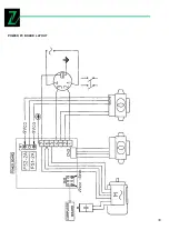
Страница 30: ...30 POWER PC BOARD LAYOUT...
Страница 31: ...31 REPLACE THE POWER PC BOARD...


