background image

24

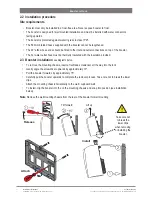
Installation instructions 

805845UK  V1.02 July 2018 - G4 Command Centre

Technical support


Tel: 0345 6 005 005  Email: [email protected]  www.zipwater.co.uk

Section 3 Filter / softener installation

An external filter / softener may be fitted to reduce the incidence of scale build up in the hot tank or may be 

supplied at the customer’s request. 

• 

All information required to mount the filter head is available 

separately in the following document :

• 

Zip scale filter head installation and operating instructions 

2017, supplied with the filter head.

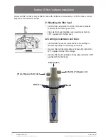
3.1 Mounting the filter head


 3.2 Cartridge installation and flush.

• 

All information required to install and flush the cartridge is 

available separately in the following documents: 

• 

Zip scale filter cartridge installation and operating instructions 

2017, supplied with the filter cartridge.

• 

Zip scale filter head installation and operating instructions 2017, 

supplied with the filter head.

(From Bypass Out) Inlet

Outlet (To Bypass in)

Insert

Remove

Insert

Remove

Flush valve

Содержание 5253UK

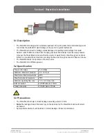
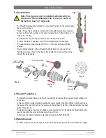
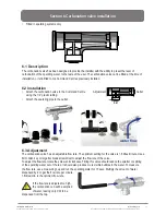
Страница 1: ...Tel 03456 005005 Email service zipindustries co uk www zipwater co uk VENTILATION ISESSENTIAL READSECTION1 VENTILATION BEFOREYOUSTART Installationinstructions Zip HydroTap G4 TheWorldsmostadvancedDri...

Страница 2: ...sparkling water and are directly compatible with the G4 Command Centre The All in One tap may be used as alternatives to the above HydroTap and mixer tap combinations The mixer tap range may be used...

Страница 3: ...nd Centre Section 7 Commercial residential Command Centre installation Section 7 1 Generic Command Centre installation instructions 30 Section 7 2 External bypass valve 31 Section 7 3 5253UK 5053UK BC...

Страница 4: ...the under counter cupboard floor supporting the Command Centre is adequate for its total weight when full of water Before commissioning Check the system has been installed correctly Check all plumbin...

Страница 5: ...he HydroTap G4 utilises a conventional refrigerant compressor to chill the water and an immersion heating element to boil the water These units are NOT designed to be used solely as sanitary fixtures...

Страница 6: ...ble is damaged it must be repaired only by a qualified technician To avoid hazards all installation procedures must be carried out by a suitably qualified tradesperson The power cable and power outlet...

Страница 7: ...roTap G4 is rated for 230V 50 60Hz AC operation supply frequency dependant upon model purchased Do not remove the cover of the appliance under any circumstances without first isolating the appliance f...

Страница 8: ...ion instructions A potable water supply connection with isolating valve inside the cupboard within reach of the flexible braided hose and positioned so that the connection point and the stop cock will...

Страница 9: ...lus unfiltered Hot and Cold Filtered Chilled and Sparkling plus unfiltered Hot and Cold Celsius Arc Cube Elite Classic HydroTaps Mixer taps Classic Vented Filtered Boiling Filtered Boiling and Ambient...

Страница 10: ...e taps All in One Classic Vented Arc Cube Elite Classic HydroTaps Mixer taps Arc Mains Cube Mains Filtered Boiling Filtered Boiling and Ambient Filtered Boiling and Chilled Filtered Boiling Chilled an...

Страница 11: ...1 2 280 x 313 x 335 11 Filtered Chilled and Sparkling 0053UK 175 0 45 1 336 x 476 x 335 36 Filtered Chilled 0061UK 175 0 3 1 336 x 480 x 335 24 Residential Command Centres Filtered Boiling Chilled an...

Страница 12: ...oth the Command Centre and booster must be installed in accordance with IEE regulations See Technical specification page 11 for power ratings Note Check all cable and hose lengths against inlet outlet...

Страница 13: ...allation 17 1 5 CS C Commercial Command Centre installation 18 1 6 BC BCS CS C Residential Command Centre installation 20 Generic requirements Important Read this section in conjunction with section 7...

Страница 14: ...lle Position vent grille on either the kick board or the cupboard ends Inlet grille should be fitted in baseboard A Cupboard back must be fully closed to prevent recirculation into cupboard from kick...

Страница 15: ...on B2 and without kick space duct fitted to the Command Centre For dual exhaust fan cut out dimensions see the instructions provided with the kit B A B2 B1 Vent tray 100mm min 1 2 4 Alternative arrang...

Страница 16: ...led through the top of the cupboard The outlet vent A should be towards the top of the door position A2 or side of the cupboard position A1 Where possible air inlet vent and the air outlet vent should...

Страница 17: ...cation sheets and installation instructions must be observed Adequate ventilation must be provided to ensure that the cupboard space temperature does not exceed 350 C 1 4 2 Preferred arrangement 4mm d...

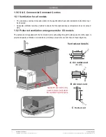
Страница 18: ...ts are not shown in these diagrams 1 5 1 Ventilation for all models The clearance envelope dimensions stated in the specification sheets and installation instructions must be observed Adequate ventila...

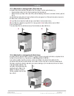
Страница 19: ...door position B1 or side position B2 and without kick space duct fitted to the Command Centre For dual exhaust fan cut out dimensions see the instructions provided with the kit B1 B2 A B 1 5 4 Altern...

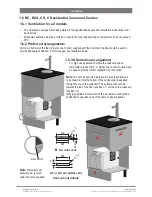
Страница 20: ...possible air inlet vent and the air outlet vent should be positioned at opposite ends of the same cupboard space 1 6 1 Ventilation for all models The clearance envelope dimensions stated in the speci...

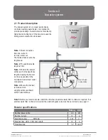
Страница 21: ...d flow rate 1 2 L min Section 2 Booster system Mount base horizontally 2 1 Product description The booster system is a compact electronically controlled auxiliary water heater It is intended to provid...

Страница 22: ...of the booster The hot water outlet hose must be thermally insulated with the insulation provided Tilt forward Lift up Release Note Remove the wall mounting chassis from the rear of the booster for w...

Страница 23: ...n the rating plate Connect the braided hoses from the BYPASS OUT fitting on the Command Centre to the water inlet of the booster blue cap and from the outlet of the booster red cap to the BYPASS IN fi...

Страница 24: ...e separately in the following document Zip scale filter head installation and operating instructions 2017 supplied with the filter head 3 1 Mounting the filter head 3 2 Cartridge installation and flus...

Страница 25: ...ulator Remove the gas cylinder from the strap Make sure the regulator knob is turned fully clockwise to the end stop before fitting Screw the regulator clockwise onto the cylinder Be aware that some C...

Страница 26: ...king a gas connection perform a leak test to check for gas leaks between regulator and cylinder and between regulator and braided hose Stage 1 Turn the gas off Using soapy water applied with a sponge...

Страница 27: ...will ensure that the volume of water that can flow through at one time is limited to a pre determined maximum providing the flow rate through it exceeds 2 litres per minute The Water Block also incor...

Страница 28: ...correct and that the filter screen see Fig 2 is inserted correctly with the convex surface facing towards the water supply 5 4 Installation Fig 2 Fit key to adjust flow Key Reset lever 5 5 Reset Proce...

Страница 29: ...let 6 3 Adjustment The carbonation valve has an adjustable flow rate The optimum setting for the valve is 1 6 litres minute Use a 6mm Allen key or large flat blade screwdriver to adjust the flow rate...

Отзывы: