
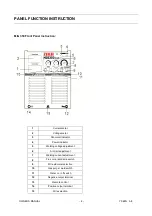


OWNER’S MANUAL - 18 - YF-48N A/0
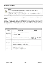
EARLIER CHECKING DIAGRAM FOR THE ABNORMAL
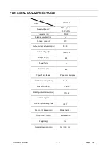
Earlier Checking Diagram For The Abnormal
Abnormal Items
Area and Item to be Inspected
and Maintained
N
o
a
rch
N
o
G
a
s
o
u
t
N
o
W
ire
F
e
e
d
in
g
B
a
d
A
rc
Ig
n
itio
n
U
n
st
a
b
le
A
rc
D
irt
o
n
E
d
g
e
o
f W
e
ld
S
e
a
W
ire
S
tick
to
P
a
re
n
t m
a
te
ria
l
W
ire
S
tick
to
C
o
n
d
u
ct
ive
T
ip
B
lo
w
h
o
le
F
o
rm
e
d
Wire Feeding Device
1. Wire feeding wheel does not match with the
diameter of wire in texturing tube
2. Crackle on wire feeding wheel, groove blocked up
or defect
3. Too tight or loose of the handle
4. Wire powder accumulated on the inlet of SUS pipe
〇
〇
〇
〇
〇
Weld Gun and Cable
Weld gun cable rolled up or over curved
Adaptability of conductive tip, wire feeding pipe and
cable diameter Worn, blocked up or deformation,
etc.
〇
〇
〇
〇
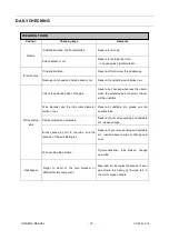
Body of weld gun
1. Loose connection of conductive tip, nozzle and
nozzle contactor
2. Contactor of weld gun body is not plunged in or
tightened well
〇
〇
Power supply cable of
weld gun as well as
cable of switch control
1. Break off (bending fatigue)
2. Damaged by weight drop
〇
〇
〇
〇
〇
Surface Condition of
Parent material and
length that wire
stretches out
1. Oil, dirty, rust and paint residues
2. Too long length of wire stretched out
〇
〇
〇
〇
〇
Output Cable
1. Cross-section of cable that connects to parent
material is not enough
2. Loose connection of
(
+
)
,
(
-
)
output cable
3. Bad electric conductivity of parent material
〇
〇
〇
Lengthened Cable
1. Cross-section of cable is not enough
2. It is rolled up or folded
〇
〇
〇
〇
Work Condition for
Welding
Welding current, voltage, angle of weld gun,
welding rate and wire length stretched out should
be confirmed once again
〇
〇
〇
〇
〇
Содержание MIG-350
Страница 1: ......
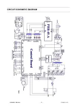
Страница 12: ...OWNER S MANUAL 11 YF 48N A 0 CIRCUIT SCHEMATIC DIAGRAM...