background image

OWNER’S MANUAL                                                                    - 5 -                                                              YF-48N    A/0


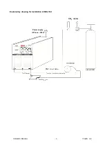
INSTALLATION INSTRUCTION 

1

  Connect the main circuit cable of the wire feeder to the corresponding output end of the machine, and fasten with 

bolts. 

2

  Connect the plug of the control circuit 6-core cable of the wire feeder to the corresponding interface of the machine 

and lock.   

3

  Connect the lug of earth wire to the corresponding output end of the machine, and fasten with bolts. 

4

  Install the CO

2

 gas meter on the gas cylinder, connect the trachea of the wire feeder to the CO

2

 gas meter tightly.   

5

  Plug the welding gun to the welding gun output socket of the wire feeder and rotate 45°clockwise. Tighten the welding 

gun  fastening  screws  with  in  turn  spanner  so  as  that  the  welding  gun  contacts  with  the  wire  feeder  output  socket 

reliably. Connect the controller plug and the gas connection to the wire feeder.   

6

  Install  the  wire  reel  loaded  with  welding  wire  on  the  shaft  bracket  of  the  wire  feeder,  select  different  wire  feeding 

groove according to the welding wire diameter.   

7

  Loosen the pressure arm, feed the welding wire into wire feeding pipe through gadget wheel and groove. Press the 

pressure arm so that the wire pressing wheel presses the welding wire tightly to prevent the welding wire from sliding. 

Do not push the pressure arm too hard, prevent the welding wire from deformation and interfering with wire feeding. 

The welding wire roll rotates clockwise to loosen the welding wire. In order to prevent the leading end of wire reel from 

loosening, it is generally fixed to the fixing hole of the wire reel. Cut off this part of welding wire to prevent the winding 

welding wire from getting struck during normal operation. 

8


This procedure shall be operated by electrician!   

Connect  proper  power  cord  to  the  distribution  box  with  corresponding capacity  according  to  the  input voltage  and 

current  of  the  welding  machine  (See  technical  parameter  table).  Do  not  connect  to  the  inappropriate  voltage  and 

make sure that the difference of power supply is within permitted range. 
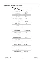


Содержание MIG-350

Страница 1: ......

Страница 2: ...truction 5 6 Panel function instruction 7 7 Welding parameter recommendation 9 8 Circuit schematic diagram 11 9 Notes or prevention measures 12 10 Questions to be run into during welding 13 11 Mainten...

Страница 3: ...ractors should be used to avoid breathing gases Arc rays Harmful to your eyes burn your skin Wear suitable protective mask light filter and protective garment to protect eyes and body Prepare suitable...

Страница 4: ...precisely controlling the short circuiting transfer and mixed transfer of welding producing excellent welding characteristic Compared with silicon controlled welding machine and welder with taps our...

Страница 5: ...rrent adjustment A 50 350 Output voltage V 16 5 31 5 Duty cycle 60 Power factor 0 93 Efficiency 85 Type of wire feeder Panasonic interface Wire feed speed m min 3 15 Post flow time S 1 5 0 5 Welding w...

Страница 6: ...racket of the wire feeder select different wire feeding groove according to the welding wire diameter 7 Loosen the pressure arm feed the welding wire into wire feeding pipe through gadget wheel and gr...

Страница 7: ...OWNER S MANUAL 6 YF 48N A 0 Explanatory drawing for Installation of MIG 350 CO2 meter Power supply 3Phase 380V...

Страница 8: ...nction When the switch is in the solid core position CO2 gas welding wire is used When the switch is in the flux cored position self shielded welding wire is applied 3 Gas examining welding change ove...

Страница 9: ...r 3 Abnormal indicator 4 Power indicator 5 Welding voltage adjustment 6 Arc trait adjustment 7 Welding current adjustment 8 Flux core sold wire switch 9 Wire diameter selection 10 Gas purge weld switc...

Страница 10: ...2 2 1 1 6 6 2 22 20 0 2 26 60 0 2 24 4 2 26 6 4 45 5 5 50 0 1 15 5 1 15 5 2 20 0 1 1 2 2 1 1 2 2 1 1 6 6 2 22 20 0 2 26 60 0 2 24 4 2 26 6 4 45 5 5 50 0 1 15 5 1 15 5 2 20 0 1 1 2 2 1 1 2 2 1 1 6 6 3...

Страница 11: ...3 35 5 4 40 0 2 25 5 2 20 0 2 25 5 H H i i g g h h w w e e l l d d i i n n g g s s p p e e e e d d 1 1 0 0 0 0 8 8 0 0 9 9 4 45 50 0 1 14 40 0 1 19 9 2 20 0 1 16 60 0 1 10 0 1 15 5 1 1 2 2 0 0 8 8 0...

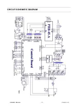
Страница 12: ...OWNER S MANUAL 11 YF 48N A 0 CIRCUIT SCHEMATIC DIAGRAM...

Страница 13: ...ke sure the working area is adequately ventilated It is important for the performance and the longevity of the machine 2 Do not over load The operator should remember to watch the max duty current Res...

Страница 14: ...substance such as oil dirt rust paint etc on the base metal MAINTENANCE WARNING The power shall be cut off completely before all maintenance overhaul works Make sure to pull out power plug before ope...

Страница 15: ...hether blowholes are blocked up while daily maintenance is carried out Some parts and components have to be cleaned or replaced if it is necessary Our original parts and components must be used for th...

Страница 16: ...the extended part too small the arc will be unstable Wire diameter and the tube inner diameter match or not Reason of unstable arc please use the suitable tube Partial winding and extended Reason of...

Страница 17: ...move and wearing out of pressed wire the narrowing of its contact surface Lead to unstable arc and wire sending Position Checking keys Remarks Torch cable 1 If torch cable over bended 2 If the metal c...

Страница 18: ...column of Abnormal items on up right of the list please inspect and maintain for the corresponding items which have mark in the column according to the following list respectively Earlier Checking Dia...

Страница 19: ...e feeding pipe and cable diameter Worn blocked up or deformation etc Body of weld gun 1 Loose connection of conductive tip nozzle and nozzle contactor 2 Contactor of weld gun body is not plunged in or...

Страница 20: ...parts failure Contact to us for repairing Replace the cable The wire feeding circuit is damaged Contact to us for repairing The wire feeder does not work Press the manual switch examine whether there...

Страница 21: ...f control board Please contact with the dealer or the factory Abnormity Indicator lamp on Power Indicator lamp on Air fan operates normally 1 IGBT damage 2 Fast recover rectifier damage 3 Control boar...

Отзывы: