background image

OWN

ER’S MANUAL                                                                            - 7 -                                                                  I-PLAS25/40 

INSTALLATION INSTRUCTION


The machine is equipped with power voltage compensation device. When the power voltage fluctuates between±15% of 

rated voltage, it still can work normally.   

When  the  machine  is  used  with  long  cables,  in  order  to  prevent  voltage  form  going  down,  bigger  section  cable  is 

suggested. If the cable is too long, it may have great affluence on the arc-striking or other performance of cutting system, 

e.g.  the  HF  arc-striking  performance  get  weak  or  the  system  work  abnormally.  So  cables  of  configured  length  are 

suggested. 

1.  Make sure intake of the machine is not blocked or covered to avoid malfunction of cooling system. 

2.  Ground the cables with section area no less than 6mm

2

 to the housing, the way is connecting screw in the back of 

the power  source  to  ground  device,  or  make  sure ground terminal  of  power socket  is  firmly  connected.  Both  ways 

can be used for absolute safety. 

3.  Use pressure-resisting air pipe to connect the air intake and compressed air source, tight the joint with hoop or other 

ways in case of gas leaking. Dry gas with suitable pressure and flow should be supplied. If your air source cannot 

meet  above  requirements,  you  should  consider  using  sole  compressor  with  enough  power  and  air-decompressing 

filter to ensure the machine work normally. 

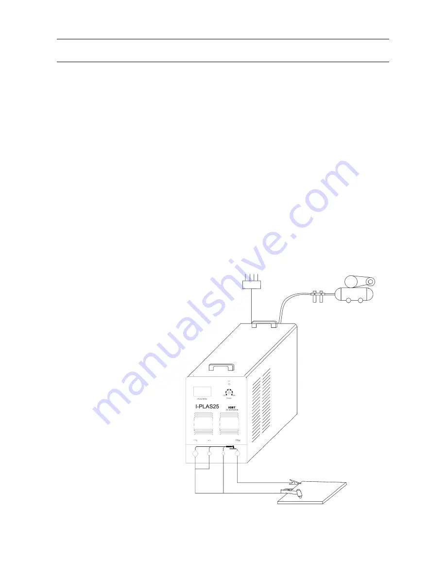
4.  Install  the  air-electricity  system  plug 

to  relevant  socket  on  the  panel  and 

fix it clockwise. Air plug of the cutting 

torch  and  arc-keeping  cable  should 

be connected to relevant socket, and 

tighten the joint screw. 

5.  Put  cable  plug  to  the  socket  on  the 

panel  and  fix  it  clockwise.  On  the 

other  hand,  clamp  the  work  piece 

with earth clamp. 

6.  According  to  input  voltage  grade, 

connect  power  cable  with  power 

supply box of relevant voltage grade. 

Make  sure  there  is  no  mistake  and 

the voltage of power supply does not 

exceed permission range.   

7.  Connect  the  cabled  following  the 

right  schematic,  next  steps  can  be 

performed then.


Machine Installation Instruction: 

Power supply   

(3phase ~380V) 

Out 

In 

Air   

compressor 

Air regulator 

Workpiece 

Earth clamp 

Cutting torch 

Содержание I-PLAS 25

Страница 1: ...ZIKA OWNER S MANUAL I PLAS 25 40...

Страница 2: ...cription 3 4 Technical parameters table 4 5 Installation instruction 5 6 Operation instruction 7 7 Panel instruction 8 8 Notes or preventive measures 10 9 Questions to be run into during welding 11 10...

Страница 3: ...ors should be used to avoid breathing gases Arc rays Harmful to your eyes burn your skin Wear suitable protective mask light filter and protective garment to protect eyes and body Prepare suitable pro...

Страница 4: ...ly by the quickly flowing air and the temperature can be up to 10000 15000 centigrade degree That forms the electrolyte estate and then form strong plasma arc It has the functions of arc initiation cu...

Страница 5: ...ltage V 269 268 Current Range A 20 80 20 100 Rate output voltage V 112 120 Duty cycle 60 60 Efficiency 85 85 Power factor 0 93 0 93 Insulation Class F F Housing Protection Class IP21 IP21 Arcing Way U...

Страница 6: ...MANUAL 5 I PLAS25 40 Front Panel Instruction of I PLAS25 1 Current meter 2 Abnormal indicator 3 Current selection knob 4 Positive output terminal 5 Negative output terminal 6 Torch switch socket 7 Pi...

Страница 7: ...PANEL FUNCTION INSTRUCTION Front Panel Instruction of I PLAS40 1 Power switch 2 Current selection knob 3 Abnormal indicator 4 Current meter 5 Negative output terminal 6 Torch switch socket 7 Pilot ar...

Страница 8: ...essure resisting air pipe to connect the air intake and compressed air source tight the joint with hoop or other ways in case of gas leaking Dry gas with suitable pressure and flow should be supplied...

Страница 9: ...on the air valve turn up the pressure adjusting knob Turn the pressure to rated value meter inside shows Kgf cm 2 and then put down the knob means increasing pressure _ means decreasing pressure 6 Sca...

Страница 10: ...working area is adequately ventilated It is important for the performance and the longevity of the machine 2 Do not over load The operator should remember to watch the max duty current Response to the...

Страница 11: ...tage is low and input cable is too long C Output current is not up to the rated value When power voltage departs from the rated value it will make the output current not matched with rated value when...

Страница 12: ...tly 4 Avoid water and steam enter into inter machine if they enter into machine please dry inter machine then check insulation of machine 5 If welding machine will not be operated long time it must be...

Страница 13: ...and there is no DC 24V output Switch indicator is lit and fan is working However press control knob of torch there is no HF arc striking sound and inner red diode is lit 1 Check if MOS K34207 of top...

Страница 14: ...broken 3 Control circuit is broken Contact factory Abnormal indicator is lit meter is normal fan is normal 1 High pressure device is broken 2 IGBT is broken 3 Rectifier broken 4 Control board is brok...

Отзывы: