background image

Translation of the original operating instructions

ZAtop


 model series SM200.40E/SM200.45E

Enclosure

A-TBA21_01-GB 2021/30 Index 003 Part.-No. 01013507-GB (EU-BD 1112)

46/64

Содержание ZA top SM200.40E

Страница 1: ... 7 B QGH 3DUW 1R 8 WRS 60 60 HDUOHVV SHUPDQHQW PDJQHW V QFKURQRXV PRWRU 2ULJLQDO RSHUDWLQJ LQVWUXFWLRQV 6WRUH IRU IXWXUH XVH ...

Страница 2: ...er of 160 mm 240 mm 12 4 5 2 Rope guard fastening in the case of a traction sheave diameter of 320 mm 13 4 5 3 Rope guard fastening in the case of a traction sheave diameter of 400 mm and 500 mm 14 4 6 Patent situation 14 5 Electrical installation 14 5 1 Safety precautions 14 5 2 EMC Directive 15 5 3 motor 15 5 3 1 Cable cross section 15 5 3 2 Type of cable 15 5 3 3 Cable length 15 5 3 4 Mechanica...

Страница 3: ... supply UPS 27 6 5 4 Automatic emergency evacuation 27 7 Faults and remedy 27 8 Service and maintenance 28 8 1 General notes on maintenance 28 8 2 Inspection intervals 28 8 2 1 Checking the air gap 29 8 3 Spare parts 29 9 Enclosure 30 9 1 Technical data 30 9 1 1 motor 30 9 1 2 Traction sheaves 31 9 1 3 Protection rating 31 9 1 4 Ambient conditions 31 9 1 5 Brake 31 9 1 5 1 Micro switch 31 9 1 5 2 ...

Страница 4: ...nce of unauthorized repairs or modifications 1 4 Copyright These operating instructions contain copyright protected information The operating instructions may be neither completely nor partially photocopied reproduced translated or put on data medium without previous explicit consent from ZIEHL ABEGG SE Infringements are liable for damages All rights reserved including those that arise through pate...

Страница 5: ...ce with the operating instructions Exceeding the limits stated in the chapter Enclosure technical data can lead to a defect in the elevator machine 2 5 Requirements placed on the personnel due diligence Persons entrusted with the planning installation commissioning and maintenance and servicing in connection with the elevator machine must have the corresponding qualifications and skills for these j...

Страница 6: ...perform maintenance work on the elevator machine when stopped The elevator machine is only to be operated within the ranges dened on the name plate of the motor Use the elevator machine only in the authorised fashion and only for the tasks and flow media specified in the order If the elevator machine is not energised no electric torque is available Releasing the brakes can cause uncontrolled acceler...

Страница 7: ... the elevator machine these personnel receive regular instruction in all relevant industrial safety and environmental protection issues and are familiar with the operating instructions and the safety instructions they contain all safety and warning notices attached to the elevator machine are never removed and remain legible 2 8 Employment of external personnel Maintenance and service work is freq...

Страница 8: ...ype Motor type and size 15 Ir Rated current A 4 Network form Connection type Rated voltage V 16 n Rated speed rpm 5 cos φ Power factor 17 Pr Rated power kW 6 JM Moment of inertia kg m2 18 Specifications of relevant standard 7 Mode 19 IPxx Protection class 8 Duty On time 20 Insulation class 9 Weight Weight kg 21 UG Generator voltage V 10 RU20 Winding resistance Ω 22 Rated frequency Hz 11 St h Trips ...

Страница 9: ...m the weather or protect it from dirt and weather until final mounting Leave the VCI paper on the grooved surface of the traction sheave as corrosion protection until the elevator machine is installed Extreme heat or cold storage temperature 20 C to 60 C must be avoided High humidity which can lead to condensation must be avoided Avoid aggressive conditions for example salt spray Maximum storage du...

Страница 10: ...sible The brake design with manual hand release must be freely accessible since the levers for brake release are moved laterally see chapter Start up manual emergency evacuation 4 2 Fastening the elevator machine On the bottom side of the socket are 4 threads To attach the elevator machine use exclusively the following screw types 4 hexagon head screws ISO 4014 M20 8 8 or 4 hexagon head screws ISO...

Страница 11: ...ing rope guard Attention Warning of hand injuries Risk of injury from reaching into the rope guard Do not carry out any activities during operation Only perform maintenance work on the elevator machine when stopped Figure 4 5 01 Rope guard The elevator machine is on the right and left fitted with rope guard 1 A 3rd rope retainer 2 is optionally available Set the rope guard to a distance of 2 3 mm f...

Страница 12: ...ap screws M6 x 12 8 8 4 and washers 5 to the relevant fixing plate 3 The slotted hole in the rope guard 1 enables the required distance to the ropes to be set at the socket cap screws M6 x 12 8 8 4 Tightening torque M6 8 8 9 5 Nm The 3rd rope retainer 2 is attached to the housing with two cheese head screws M8 x 16 8 8 6 and washers 7 or for traction sheave diameter 240 mm with one cheese head scre...

Страница 13: ... 4 5 3 Rope guard fastening in the case of a traction sheave diameter of 400 mm and 500 mm Adjustability on both sides 5 30 Normal wrap angles 30 185 Figure 4 5 3 01 Rope guard for traction sheave diameter 400 mm 500 mm Figure 4 5 3 02 Rope guard optionale 3 rd rope retainer The rope guard 1 is fastened in each case with two hexagon head screws M6 x 12 8 8 4 and washers 5 to the relevant fixing pla...

Страница 14: ...l tool Never clean electrical equipment with water or similar liquids 5 2 EMC Directive Compliance with the EMC directive 2014 30 EU only applies to this product if frequency inverters tested and recommended by ZIEHL ABEGG SE are used and they are installed in line with the associated operating instructions and are EMC compatible If this product is improperly integrated into a system or is combine...

Страница 15: ...ts or uncontrolled acceleration of the elevator machine Figure 5 3 5 01 1 Frequency inverter 2 Motor temperature monitoring 5 3 6 Protective earth connection In accordance with EN 50178 section 5 2 11 and 5 3 2 1 the protective earth connection must have a cross section of at least 10 mm In the case of protective conductors 10 mm an additional protective conductor must be connected The cross secti...

Страница 16: ...st voltage for PTC thermistors 2 5 VDC When monitoring with a temperature sensor PT100 the monitoring unit must be set to the limit value C specified in the connection diagram 5 3 7 1 Connection diagram with PTC thermistor PTC Figure 5 3 7 1 01 1 Shielding 2 1 PTC thermistor per phase 3 Attention Do not apply any voltage 2 5 V 5 3 7 2 Connection diagram with temperature sensor PT100 Figure 5 3 7 2 ...

Страница 17: ...and extension cable Available as an option Connection and extension cable version Shielded twisted pair cable Absolute encoder ECN1313 EnDat ECN1313 SSI AE S64 BISSC 05 ZA ERN1387 AE S64 SinCos 07 AE Adapter ca bles Connection Jumper M16 x 0 75 SV120 x x x Jumper M23 x 1 x x x Jumper D SUB 15 pin x x x Wire end sleeves x Cable length 0 22 m 0 245 m x x x x x x 0 35 m x 0 56 m x x 1 8 m x 5 0 m x 7...

Страница 18: ...ack A cosine L 16 13 A Analog track A invers cosine invers M 13 14 B Analog track B invers sine invers Table 5 4 2 1 5 4 2 2 Absolute encoder AE S64 BISSC 05 ZA PIN Function Designation Jumper D SUB 15 pole 1 DATA Data line for communication with the absolute encoder 2 DATA Data line inverse 3 4 VCC Voltage supply 5 V DC 5 GND Power supply ground 6 7 B Analog track B sine 8 9 CLOCK Clock signal in...

Страница 19: ...C Voltage supply 5 V DC White GND Power supply ground Blue B Analog track B sine Violet D Commutation signal inverse inverse sine Grey pink Z Reference signal Red blue Z Reference signal inverse Green A Analog track A cosine Yellow A Analog track A invers cosine invers Red B Analog track B invers sine invers Table 5 4 2 4 5 4 3 Offset Unless otherwise agreed the absolute encoder offset is set to 0...

Страница 20: ...state of both brake circuits have to be monitored separately Release monitoring for the brakes is carried out by a microswitch or inductive proximity switch For technical data see chapter Appendix Technical data Microswitch or inductive proximity switch 5 5 4 Brake control 5 5 4 1 Contactorless ZAsbc4 Electronic and noise free activation of the brake The brake operating mode is set on site For inf...

Страница 21: ...with power when fastened to the motor and after having connected the protective conductor of the motor at the control and the motor side The brakes must be protected with varistors against overvoltage from switching operations The varistor must lie directly on the coil or its connections 5 5 6 Connection diagram Brake wiring diagram with micro switch Figure 5 5 6 01 1 Brake release monitoring 2 Br...

Страница 22: ...lation The forced ventilation is optional and can be added afterwards 5 6 1 Technical data Voltage 220 240 V Frequency 50 60 Hz Power 20 19 W Current 0 125 0 11 A Table 5 6 1 5 6 2 Connection diagram Figure 5 6 2 01 1 Thermal contact Translation of the original operating instructions ZAtop model series SM200 40E SM200 45E Electrical installation A TBA21_01 GB 2021 30 Index 003 Part No 01013507 GB ...

Страница 23: ...directions with a half load The measured currents should correspond as closely as possible The difference between the measured currents should not show a variation of more than 10 Half load test with release of the brake only The short circuit of the motor windings if installed should be disabled for the duration of the half load test With a half load and the brake released the car may not move Af...

Страница 24: ...the shaft the elevator machine is usually not accessible A handwheel is unnecessary in such a layout With gearless elevator machines in machine rooms a handwheel does not make any sense because there is no gear reduction That is because due to the low moment arm of force only slight force can be applied A handwheel could even present a hazard as even with only a slight imbalance in the installatio...

Страница 25: ...insertion positions of the levers for hand release Figure 6 5 2 02 Brake not opened Example for hand release lever position Figure 6 5 2 03 Brake manuell released Example for hand release lever position Attach the levers for hand release to the brake in any position The brake is released via simultaneous movement of both levers for hand release The direction is not of any significance in this regar...

Страница 26: ... or remove it and loosen the brake rotor carefully from the armature plate Brake switching noises Brake is switched on the DC side Modify the control to AC switching for nor mal operation Fit an additional protective circuit Air gap of brake too big Replace the brake rotors Special tool re quired Contact the customer service of ZIEHL ABEGG SE Brake does not open Power supply too low The voltage at...

Страница 27: ...ection intervals During commissioning or after the first 3 months every year Distance of the rope guard x x Check vibration isolation The thickness of the vibration isolation must be the same on the right and left x x Checking the air gap of the brake x x Visual inspection of the mounting screws on the hous ing brakes and traction sheave The locking compound must be free of damage x x Check the tra...

Страница 28: ...ive influence on the function or safety of the elevator machine ZIEHL ABEGG SE will accept no liability or warranty for damages resulting from use of unapproved spare parts Figure 8 3 01 Spare parts Available spare parts 1 Absolute encoder 2 Complete brake 2 1 Brake rotors with O rings 2 2 Micro switch for brake 2 3 Inductive proximity switch for brake 3 Traction sheave 4 Rope guard 5 Rope retainer...

Страница 29: ... 106 124 173 122 95 90 Table 9 1 2 9 1 3 Protection rating Component Protection rating motor IP 21 Forced ventilation IP 20 Absolute encoder IP 40 Brake electrical IP 54 Brake mechanical IP 10 Complete machine IP 21 Table 9 1 3 9 1 4 Ambient conditions The user must ensure that the specified ambient conditions are observed Ambient temperature for operation C 0 to 40 Humidity Maximum 95 condensation...

Страница 30: ...g mA V DC 10 50 24 Table 9 1 5 1 9 1 5 2 Inductive proximity switch Operating voltage V DC 10 30 Rated operating current mA DC 100 Output functions NC contact gauge zero Table 9 1 5 2 For further information refer to the Appendix Brake operating instructions Assembly and adjust ment of the release monitor with inductive proximity switch chapter Translation of the original operating instructions ZA...

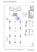
Страница 31: ...et 9 2 1 Dimension sheet ZAtop SM200 40E SM200 45E Translation of the original operating instructions ZAtop model series SM200 40E SM200 45E Enclosure A TBA21_01 GB 2021 30 Index 003 Part No 01013507 GB EU BD 1112 31 64 ...

Страница 32: ... of conformity Translation english A KON16_01 GB 2021 28 Index 003 Manufacturer ZIEHL ABEGG SE Heinz Ziehl Straße 74653 Künzelsau Germany The manufacturer shall bear sole responsibility for issuing this EC EU declaration of conformity Product description ZAtop Gearless elevator machine Type SM160 SM190 SM200 SM225 SM250 The type specifications contain further additions for different versions for ex...

Страница 33: ...used EN 12015 2014 Electromagnetic compatibility Productfamily standard for lifts escalators and moving walks Emission This declaration relates exclusively to the product in the state in which it was placed on the market and excludes components which are added and or operations carried out subsequently by the final user The authorised representative for the assembly of the technical file is Mr Rolan...

Страница 34: ...9 4 Operating instructions brake Translation of the original operating instructions ZAtop model series SM200 40E SM200 45E Enclosure A TBA21_01 GB 2021 30 Index 003 Part No 01013507 GB EU BD 1112 34 64 ...

Страница 35: ...Translation of the original operating instructions ZAtop model series SM200 40E SM200 45E Enclosure A TBA21_01 GB 2021 30 Index 003 Part No 01013507 GB EU BD 1112 35 64 ...

Страница 36: ...Translation of the original operating instructions ZAtop model series SM200 40E SM200 45E Enclosure A TBA21_01 GB 2021 30 Index 003 Part No 01013507 GB EU BD 1112 36 64 ...

Страница 37: ...Translation of the original operating instructions ZAtop model series SM200 40E SM200 45E Enclosure A TBA21_01 GB 2021 30 Index 003 Part No 01013507 GB EU BD 1112 37 64 ...

Страница 38: ...Translation of the original operating instructions ZAtop model series SM200 40E SM200 45E Enclosure A TBA21_01 GB 2021 30 Index 003 Part No 01013507 GB EU BD 1112 38 64 ...

Страница 39: ...Translation of the original operating instructions ZAtop model series SM200 40E SM200 45E Enclosure A TBA21_01 GB 2021 30 Index 003 Part No 01013507 GB EU BD 1112 39 64 ...

Страница 40: ...Translation of the original operating instructions ZAtop model series SM200 40E SM200 45E Enclosure A TBA21_01 GB 2021 30 Index 003 Part No 01013507 GB EU BD 1112 40 64 ...

Страница 41: ...Translation of the original operating instructions ZAtop model series SM200 40E SM200 45E Enclosure A TBA21_01 GB 2021 30 Index 003 Part No 01013507 GB EU BD 1112 41 64 ...

Страница 42: ...Translation of the original operating instructions ZAtop model series SM200 40E SM200 45E Enclosure A TBA21_01 GB 2021 30 Index 003 Part No 01013507 GB EU BD 1112 42 64 ...

Страница 43: ...Translation of the original operating instructions ZAtop model series SM200 40E SM200 45E Enclosure A TBA21_01 GB 2021 30 Index 003 Part No 01013507 GB EU BD 1112 43 64 ...

Страница 44: ...Translation of the original operating instructions ZAtop model series SM200 40E SM200 45E Enclosure A TBA21_01 GB 2021 30 Index 003 Part No 01013507 GB EU BD 1112 44 64 ...

Страница 45: ...Translation of the original operating instructions ZAtop model series SM200 40E SM200 45E Enclosure A TBA21_01 GB 2021 30 Index 003 Part No 01013507 GB EU BD 1112 45 64 ...

Страница 46: ...Translation of the original operating instructions ZAtop model series SM200 40E SM200 45E Enclosure A TBA21_01 GB 2021 30 Index 003 Part No 01013507 GB EU BD 1112 46 64 ...

Страница 47: ...Translation of the original operating instructions ZAtop model series SM200 40E SM200 45E Enclosure A TBA21_01 GB 2021 30 Index 003 Part No 01013507 GB EU BD 1112 47 64 ...

Страница 48: ...Translation of the original operating instructions ZAtop model series SM200 40E SM200 45E Enclosure A TBA21_01 GB 2021 30 Index 003 Part No 01013507 GB EU BD 1112 48 64 ...

Страница 49: ...Translation of the original operating instructions ZAtop model series SM200 40E SM200 45E Enclosure A TBA21_01 GB 2021 30 Index 003 Part No 01013507 GB EU BD 1112 49 64 ...

Страница 50: ... adjustment of the release monitor with microswitch Translation of the original operating instructions ZAtop model series SM200 40E SM200 45E Enclosure A TBA21_01 GB 2021 30 Index 003 Part No 01013507 GB EU BD 1112 50 64 ...

Страница 51: ...Translation of the original operating instructions ZAtop model series SM200 40E SM200 45E Enclosure A TBA21_01 GB 2021 30 Index 003 Part No 01013507 GB EU BD 1112 51 64 ...

Страница 52: ...ent of the release monitor with inductive proximity switch Translation of the original operating instructions ZAtop model series SM200 40E SM200 45E Enclosure A TBA21_01 GB 2021 30 Index 003 Part No 01013507 GB EU BD 1112 52 64 ...

Страница 53: ...Translation of the original operating instructions ZAtop model series SM200 40E SM200 45E Enclosure A TBA21_01 GB 2021 30 Index 003 Part No 01013507 GB EU BD 1112 53 64 ...

Страница 54: ...U Declaration of Conformity for Brake Translation of the original operating instructions ZAtop model series SM200 40E SM200 45E Enclosure A TBA21_01 GB 2021 30 Index 003 Part No 01013507 GB EU BD 1112 54 64 ...

Страница 55: ...Translation of the original operating instructions ZAtop model series SM200 40E SM200 45E Enclosure A TBA21_01 GB 2021 30 Index 003 Part No 01013507 GB EU BD 1112 55 64 ...

Страница 56: ... 6 EU Type Examination Certificate Translation of the original operating instructions ZAtop model series SM200 40E SM200 45E Enclosure A TBA21_01 GB 2021 30 Index 003 Part No 01013507 GB EU BD 1112 56 64 ...

Страница 57: ...Translation of the original operating instructions ZAtop model series SM200 40E SM200 45E Enclosure A TBA21_01 GB 2021 30 Index 003 Part No 01013507 GB EU BD 1112 57 64 ...

Страница 58: ...Translation of the original operating instructions ZAtop model series SM200 40E SM200 45E Enclosure A TBA21_01 GB 2021 30 Index 003 Part No 01013507 GB EU BD 1112 58 64 ...

Страница 59: ...Translation of the original operating instructions ZAtop model series SM200 40E SM200 45E Enclosure A TBA21_01 GB 2021 30 Index 003 Part No 01013507 GB EU BD 1112 59 64 ...

Страница 60: ...Translation of the original operating instructions ZAtop model series SM200 40E SM200 45E Enclosure A TBA21_01 GB 2021 30 Index 003 Part No 01013507 GB EU BD 1112 60 64 ...

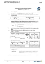
Страница 61: ... s m s m s m s SM200 40E SM200 45E 160 435 500 3 64 4 19 1 82 2 09 SM200 40E SM200 45E 200 435 500 4 56 5 24 2 28 2 62 SM200 40E SM200 45E 240 435 500 5 47 6 28 2 73 3 14 SM200 40E SM200 45E 320 435 500 7 29 8 38 3 64 4 19 SM200 40E SM200 45E 400 435 500 9 11 10 47 4 56 5 24 SM200 40E SM200 45E 500 435 500 11 39 13 09 5 69 6 54 9 8 Calculation proof Translation english A BN21_01 GB 2021 09 Index 0...

Страница 62: ...tion and design Corrigendum to DIN 6892 2012 08 DIN 5466 1 2000 10 Splined joints calculation of load capacity Part 1 General basis FKM Guideline 2012 Analytical strength assessment of mechanical com ponents Construction drawing A 20 121 0031 Index 000 dated 05 08 2020 Permissible shaft materials Steel DIN EN 10083 3 2007 01 42CrMo4 QT 1 7225 QT Steel DIN EN 10083 3 2007 01 42CrMo4 QT 1 7227 QT St...

Страница 63: ...and an unmovable mounting of the bearings in each direction is presupposed The machine frame and the points of force introduction have to be designed regarding construction and strength appropriate to the forces imposed on the bearings It should be noted that on the brake side only braking torque is applicable because the calculation does not take into account the additional transverse forces due ...

Страница 64: ...UYLFH Telefon 49 7940 16 308 Telefax 49 7940 16 249 drives service ziehl abegg com Firmenzentrale ZIEHL ABEGG SE Heinz Ziehl Straße 74653 Künzelsau Deutschland Telefon 49 7940 16 0 Telefax 49 7940 16 249 drives ziehl abegg de www ziehl abegg com ...

Отзывы: