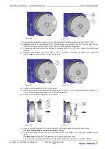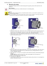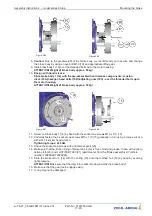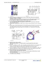
Figure 8-19
Figure 8-20
Brake wiring diagram with micro switch
Figure 8-21
1 Brake release monitoring
2 Brake
3 Shown with currentless brake
Brake wiring diagram with inductive proximity
switch
Figure 8-22
1 Brake release monitoring
2 Brake
3 Minimum strength 2 mA DC
4 Operating voltage range 10 - 30 V DC
5 Shown with currentless brake
40. Connect the magnet coils, the release monitoring and varistors (4) according to the wiring
diagram (28), see Figure 8-21 and Figure 8-22, inside the top cover of the junction box (1).
41. Fit strain reliefs (3).
42. Close the cover (1) of the junction box.
43. Perform brake test (see chapter "Brake operating instructions - brake test" in the appendix at the
original operating instructions).
44. Carry out the alignment of the absolute encoder (9) corresponding to the original operation
instructions of the frequency inverter.
9 Functional test on microswitch/inductive proximity switch for re-
lease monitor
After mounting of the brake, a functional test must be performed on the micro switches/inductive
proximity switches (see chapter "Brake operating instructions - release monitor" at the original operat-
ing instructions).
If the function is not available, please check the causes that may prevent the actuation of the micro
switches/inductive proximity switches (see chapter "Brake operating instructions - release monitor" in
the appendix). The micro switches/inductive proximity switches will otherwise have to be readjusted
(see the chapter "Assembly and adjustment of release monitor with micro switches or inductive
proximity switches" in the appendix at the original operating instructions).
Assembly instructions
–
model series ZAtop Functional test on microswitch/inductive proximity switch for release
monitor
A-TIA21_08-GB 2021/21 Index 001
Part.-No. 01013509-GB
15/20


