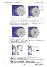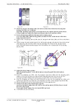
Figure 8-12
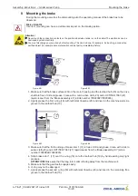
Figure 8-13
25.
Check the air gap "A" between the coil carrier and armature disk when de-energised:
Air gap: 0.40 mm
≤
"A"
≤
0.60 mm
See brake operating instructions in the appendix to the original operating instructions.
✓
If the air gaps are outside the tolerance, please contact our customer service.
26.
On the brake design with hand release system, lightly grease
2 x 4 steel balls (13A) (with bearing grease) and insert in the counterbores in the brake
body 2 spool carrier (13).
27. Slide the two connecting pieces (13B) onto the hexagon head bolts (16B) with the counterbores
fi
rst.
28. Lightly grease the axial needle cages (13C) with bearing grease and attach to the centring collar
of the adjusting nuts (13D) and then screw the adjusting nuts (13D) onto the hexagon head
bolts (16B) with the axial needle cages (13C)
fi
rst until they are in contact with the connecting
pieces (13B).
Figure 8-14
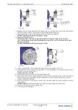
Figure 8-15
29.
Adjust the hand release system:
Slide the adjusting plate 1.8 mm (24) between an adjusting nut (16C) and armature
disk (14).
30. Screw the adjusting nut (13D) onto the hexagon head bolt (16B) until the adjusting plate
clamps 1.8 mm (24) and then turn back until the adjusting plate (24) can be removed. The
hexagon head bolt (16B) can be held in place using the slot on the end of the screw.
31. Coat the threaded pin (13E) with LOCTITE
®
243, screw into the adjusting nut (13D) with
tightening torque 4 Nm and thus clamp the adjusting nut (13D) on the hexagon head bolt (16B).
32. Repeat the adjustment of the hand release system on the opposite side.
33.
Check the function of the hand release system:
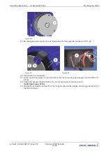
Insert the two hand release bars (21) into the connecting pieces (13B) and move around
45
°
to the left or right.
The required hand release force is around 200 N per lever.
34. The shaft must now rotate freely.
Assembly instructions
–
model series ZAtop
Mounting the brake
A-TIA21_08-GB 2021/21 Index 001
Part.-No. 01013509-GB
13/20


