


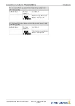

Connection diagram for motors with three speeds
KT00047A
14.04.2016
M
1 ~
ECQ
BU
rpm 1
BN
BK
C
N
L1
M
1 ~
ECQ
BU
BN
BK
C
N
L1
M
1 ~
ECQ
BU
BN
BK
C
N
L1
rpm 2
rpm 3
N, L1
Line voltage
rating plate
C
Control input speed
BK
black
BN
brown
BU
blue
rpm 3
Speed step 3
rpm 2
Speed step 2
rpm 1
Speed step 1
If the black wire is connected with the brown
wire, the motor runs at speed step 3
If the black wire is connected with the blue wire,
the motor runs at speed step 2
If the black wire is not connected, the motor runs
at speed step 1
Danger due to electric current
A dangerous voltage (maximum line voltage is applied at the
black
connecting wire
(speed control input) when it is not used (speed step 1). Therefore this wire must be
connected to a terminal for insulation.
Assembly instructions
FE2owlet-ECQ
Mounting
L-BAL-F062-GB 2022/20 Index 004
Part.-No. 00702389-GB
14/24