


-15-
2
1
C
7/8
1
9
6-3/4
5
1-1/16
0.125
(4) 1/4 DIA HOLES THRU
0.38
(2
PLACES
)
2.75
0.88
1/2
0.50
0.25
2.00
0.75
0.75
1-9/16
7.000
20-3/4
18.75
0.187
(2) PLACES
16-1/4
0.12
(3
PLACES
)
0.81
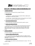
Lights are to be mounted on the outboard side on each set of PTS units.
*FLASHER
(
)
( + )
12VDC
POWER SUPPLY
(BY OTHERS)
(CAP)
LIMIT SWITCH
( + )
(
)
(
)
( + )
4' WHITE
4' BLACK
88
87
SPLICE CONNECTION
CLEARANCE LIGHT
MASTER PTS UNIT
SLAVE PTS UNIT
FIGURE 5.
FLASHING
LIGHT KIT
MODEL PTS-FLK
Wiring System:
1. One white wire 4' long
(88) and one black wire 4'
long (87) are provided for
each light (75).
2. Snap plug connec-
tions (86) will be attached
to each wire, ready to
plug into lights prior to
mounting, or wires may be
soldered to the light.
3. In-line splices (83) are
provided. Seventh splice
to be connected to third
wire in the limit switch
harness (77). This wire
may be used for indicator
light in the cab.
4. Flasher (79) should be
mounted in a weather-
proof location and
mounted in the clip (89)
provided.
If your PTS System was purchased prior to
January 1, 1997, holes will need to be drilled as
shown in the base cover plates (left) and tank
cover plates (below).
Limit switch (76) makes contact with the shelf
(right or left) casting to shut off the lights.
83
75
76
79
Содержание QUIC-LIFT PTS
Страница 20: ... 20 FIGURE 12 ELECTRICAL SYSTEM ...
Страница 24: ... 24 FIGURE 17 TANK BOX COMPONENTS 10 42 10 17 110 32 18 42 33 ...
Страница 25: ... 25 This page intentionally left blank ...
Страница 26: ... 26 This page intentionally left blank ...
Страница 27: ... 27 This page intentionally left blank ...


