Installation
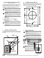
Figure 2 – Desktop Keypad switch circuits
The “- X -” symbols shown above represent circuit board traces that are used to create a
common reference for all switch common leads. If your application requires each switch
to be isolated then these circuit board traces can be cut. To do so you’ll need to remove
the circuit board from the metal housing as these traces are located on the top side of the
circuit board (the side with the pushbuttons). The traces are located near the connector as
shown above in Figure 2.
Figure 3 – Desktop Keypad switch identification
1
2
3
4
10
025-9636A
Содержание 025-9636A
Страница 1: ...Zetron Desktop Keypad 025 9636A...