

2.
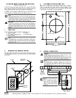
SCF REMOTE KEYPAD TEMPLATE
NOTE: Verify dimensions on printed page before using as a template.
Hold this page against the panel where the remote keypad is to be
mounted, and use a center punch to mark the location of the three holes.
The dotted line is the outline of the remote keypad.
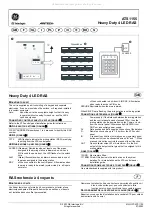
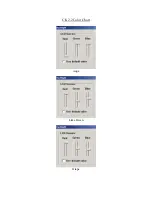
4.
WIRING CONNECTIONS
WARNING!
Improper wiring may result in damage to the Remote Keypad. Keep
the remote keypad cable away from power wiring.
The Belden and Carol cables specified consist of two twisted pairs. Make
sure one twisted pair is used for power and the other is used for serial
communications. Do not mix connections between twisted pairs
Note 1:
The supplied cable can be used for distances up to 8 feet in low-
noise environments. For distances up to 100 feet, or in high-noise
environments, use Belden 9842, Carol C4842, or equivalent (24 gauge
minimum) wire only.
SCF SERIES REMOTE KEYPAD INSTRUCTIONS
(Manual Number: KF01G)
The SCF Series Remote Keypad option (844-200) allows the SCF Series
drive to be programmed and controlled from up to one hundred feet away.
When properly mounted, the remote keypad is rated NEMA 4X.
In addition to the functions available on the front of the SCF drive, the
remote keypad has Start/Stop and Forward/Reverse functions.
Note:
The Remote Keypad option will only work with SCF drives that have
parameter version “309” or “312”. It will not work with SCF drives that
have the High Frequency or PI Setpoint Control options. The parameter
version appears momentarily on the drive display when it is powered up,
and also appears on a small label on the drive’s heatsink.
WARNING!
If OEM mode is selected (using Parameter 48), and if the OEM Default
setting for Parameter 14 and/or 15 is “01”, the remote keypad will
be disabled, and the
STOP
key WILL NOT work. Refer to the SCF
Installation and Operation Manual for information on OEM Default
settings.
1.
PARTS LIST
The SCF Remote Keypad kit includes the following parts:
(1) Remote Keypad
(1) Gasket
(2) Self-tapping Mounting Screws
(1) Instruction Sheet
(1) Eight foot cable
Note:
The supplied cable can only be used for distances up to 8 feet in low-
noise environments. For distances up to 100 feet, or in high-noise
environments, use Belden 9842, Carol C4842, or equivalent (24 gauge
minimum) wire only.
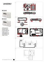
REMOTE KEYPAD
(BACK VIEW)
JUMPER
(See NOTE 2
in Section 5)
TXA
TXB
11
2
UP
TXA TXB
1
11
2
2
Cable included with kit
does not have a shield
SCF TERMINAL STRIP
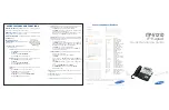
1/8” hole
1/8” hole
1.57”
1.32”
1.38” to 1.5” hole
3.38”
2.19”
UP
Max Depth = 0.72”
PANEL
REMOTE
KEYPAD
GASKET
MOUNTING
SCREWS
3.
MOUNTING THE REMOTE KEYPAD
The diagram below illustrates how to mount the remote keypad to a panel.
Use the template in Section 2 to mark the location of the mounting holes
on the panel.
Note 2:
TB-11 can supply up to 50 mA of
power, and the remote keypad
requires 40 mA. To drive auxiliary
relays using the open-collector
outputs, an external power supply
is required.
• 630 Douglas Street • Uxbridge, MA 01569 • USA • Sales (800) 217-9100 • Service (508) 278-9100 • www.lenze-actech.com