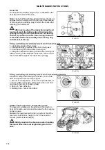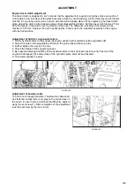
Bleeding of hydraulic clutch circuit
PGPPN154
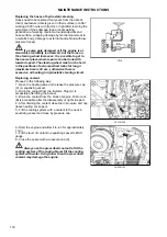
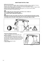
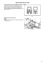
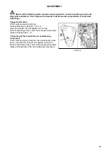
The liquid reservoir for control of the clutch is located on the left in front of the tractor cabin and is accessible
when the front engine bonnet is open.
During bleeding observe the amount of liquid in the balancing tank to avoid intake of air.
1. Add the missing amount of the fluid in the equalizing vessel to the max. amount.
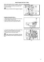
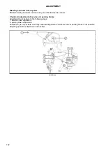
2. Remove the rubber cap, install the hose on the bleeder screw (1) on the tripping cylinder of the clutch
located on the left side of the tractor near the clutch housing and immerse the other end to the bottom of the
transparent vessel partly filled with the fluid for control of the clutch. The bleeder screw must be permanently
under pressure to prevent air penetration through its threads, therefore when doing this place the vessel at
least 300 mm above the bleeder screw.
3. Press fully the clutch pedal and keep it pressed in the lower position.
4. Release the bleeder screw by 1/4 revolution max.
5. Tighten the bleeder screw.
6. Release the clutch pedal.
7. Repeat the procedure until no air bubbles come out of the hose.
8. Remove the hose from the bleeder screw and install the rubber cap back on it.
Only new fluid can be added in the equalizing vessel. After two years of operation, replacement
of the fluid in the whole clutch release hydraulic circuit must be performed.
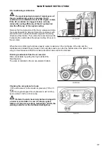
Adjustment of the pneumatic control of the PTO shaft clutch
The clearance between the release bearing and the clutch
release levers must be adjusted to 4 mm and must not fall
below 2.5 mm in operation.
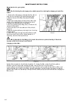
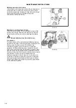
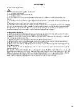
The adjusting rod is located on the left side of the tractor
at the clutch housing.
Adjustment procedure:
With the tractor stopped, engine stopped:
Loosen the nut (3) and let the air out
Loosen the locking nut (1)
Draw (shorten) the rod (2) until the release bearing
touches the clutch release levers, the touch is signaled by
a significant increase in the force required to rotate the rod
(2).
Loosen (extend) the rod (2) by 1 and 4/6 turn.
Secure the rod (2) by tightening the locking nut (1).
Tighten the nut (3).
P18N085
ADJUSTMENT
184
Содержание Proxima CL 100
Страница 1: ...OPERATOR S MANUAL PROXIMA CL 03 2018 Tractor is Zetor Since 1946 80 90 100 110...
Страница 3: ...2...
Страница 11: ...10...
Страница 33: ...NOTES 32...
Страница 91: ...NOTES 90...
Страница 111: ...NOTES 110...
Страница 131: ...NOTES 130...
Страница 147: ...Fuse panel B P18N083 ELECTRICAL INSTALLATION 146...
Страница 163: ...NOTES 162...
Страница 181: ...NOTES 180...
Страница 187: ...NOTES 186...
Страница 203: ...NOTES 202...
Страница 208: ...207...
Страница 210: ...Made in EU www zetor com zetor zetor com...

