EXPro Installation Manual
Approved Document No: GLT-212-7-1
Page 28
Issue: 1.7 Author: MF/NRPJ Date: 05/07/2021
1
2
3
4
5
6
7
8
9
10
16
11
12
13
14
15
19
20
17
CONNECTIONS
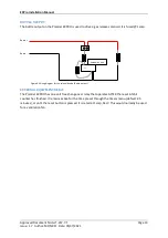
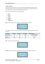
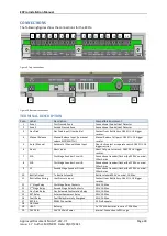
The following figures show the connections for the EXPro
Figure 9. Top connections
Figure 10. Bottom connections
TERMINAL DESCRIPTION
Conn
Label
Description
Compatible Equipment
1
Zone 1
First Crossed Zone
Conventional Smoke/Heat Detector
2
Zone 2
Second Crossed Zone
Conventional Smoke/Heat Detector
3
Gas Fired
Gas Fired Input (from bottle)
Contact from Bottle Assy. 18k EOL. 1K trigger
resistor.
4
Manual Release
Manual Release Input (to manual
release MCP/SWITCH)
Manual Release Call point. 18k EOL. 1K trigger
resistor.
5
Auto / Manual
Automatic / Manual Mode Input
Door lock contact or separate switch. 18k EOL. 1K
trigger resistor.
6
Abort
Abort Input
Abort Call point or switch. 18k EOL. 1K trigger
resistor.
7
S1A
First Stage Sounder Circuit A
Conventional sounder/flasher/bell 29.5V nominal,
150mA max
8
S1B
First Stage Sounder Circuit B
Conventional sounder/flasher/bell 29.5V nominal,
150mA max
9
S2
Second Stage Sounder Circuit
Conventional sounder/flasher/bell 29.5V nominal,
150mA max
10
Bottle Output
To Bottle Solenoid
Bottle solenoid 29.5V nominal, 1A Max.
11
Bottle Monitoring
Low Pressure Input
Contact from Bottle Assy. 18k EOL. 1K trigger
resistor.
12
1
st
Stage Relay
First Stage Relay Contacts
SELV, 1A Max
13
2
nd
Stage Relay
Second Stage Relay Contacts
SELV, 1A Max
14
Gas Fired Relay
Gas Released Confirmation Relay
SELV, 1A Max
15
EXT Relay
External Equipment Relay
SELV, 1A Max
16
Fault Relay
Fault Relay Normally Energised
SELV, 1A Max
17
REP B A
RS485 Connection
EX Pro Repeater
18
Not Used
-
-
19
+BAT-
Battery
1 x 12V SLA batteries in series 7.2Ah Max
20
24VDC IN
24V DC Main Power
Internal Connection to PSU cage

