The Zeroplus Logic Analyzer
Installation Guide
The Zeroplus Logic Analyzer Installation Guide
Page 26
Task 3. Signal/Bus Trigger Edge Setup
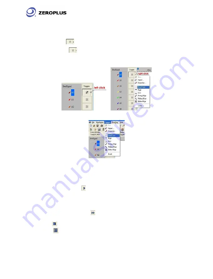
Highlight a designated signal, and then set its required trigger edge.
1. Left click
to set the signal trigger edge as shown in Fig 3-16.
2. Right click
to set the signal trigger edge as shown in Fig 3-17.
3. Click Trigger on the menu bar and choose a trigger from the list of triggers
as shown in Fig 3-18.
Fig 3-16 – Trigger Left click
Fig 3-17 – Trigger Right Click
Fig 3-18 – Trigger menu
Task 4. Run to Acquire Data
1. Single Run
Click the Single Run
icon from the tool bar or press START button on top of
Logic Analyzer (or press F5), then activate the signal from the DUT to the Logic
Analyzer to acquire the data shown in the wave display area.
2. Repetitive Run
Click the Repetitive Run
icon from the tool bar, then activate continuous
signal to the Logic Analyzer to acquire the repetitive Data, and then click the
stop
icon to end the repetitive run.
Tip:
Click icon to view all the data, and then select the wave analysis tools to
analyze the waves.


