Fixed Hoist Test Facility Operation and Maintenance Manual
ZOM-12000-7 rev 0
Page 6 of 24
This manual contains proprietary information and is not to be copied or disclosed without written
permission from Zephyr International LLC. Copyright 2006-2008
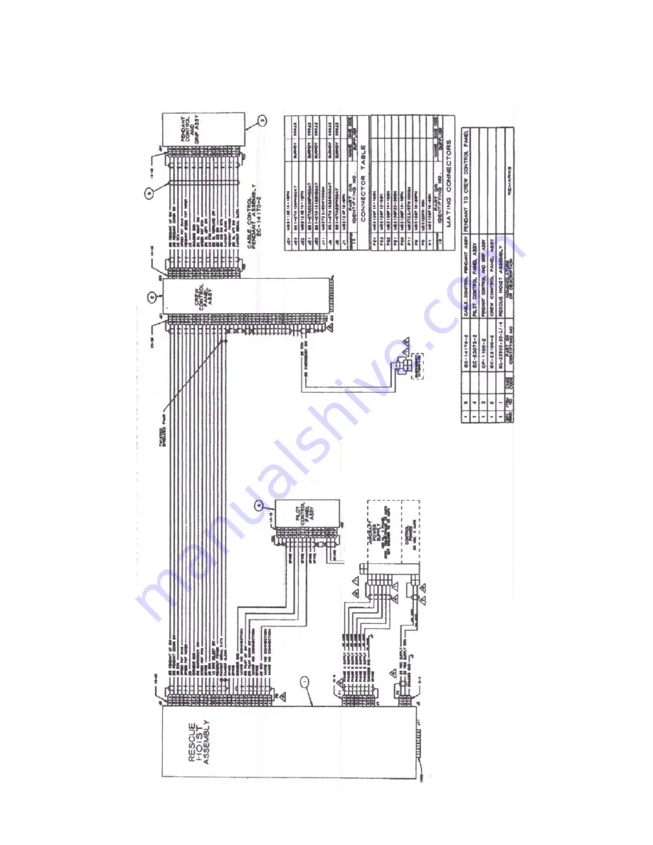
System Interconnect Diagram


