


18
■
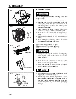
STARTING ENGINE
The cutting head will start rotating upon the
engine starts.
1. Rest the unit on a flat, firm place. Keep the
cutting head off the ground and clear of
surrounding objects as it will start rotating upon
starting of the engine.
2. Push the primer pump several times until
overflown fuel flows out in the clear tube. (OP1)
3. Move the choke lever to the closed position.
(OP2)
4. Set the ignition switch to the “start” position.
(OP3)
5. While holding the unit firmly, pull out the starter
rope quickly until engine fires. (OP4)
(1) choke lever (2) close (3) open
(4) ignition switch (5) start (6) stop
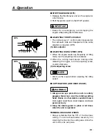
• Avoid pulling the rope to its end or returning it by
releasing the knob. Such actions can cause
starter failures.
6. Move the choke lever downward to open the
choke. And restart engine. (OP2)
7. Allow the engine to warm up for a several
minutes before starting operation.
1. When restarting the engine immediately after
stopping it, leave the choke open.
2. Overchoking can make the engine hard to start
due to excess fuel. When the engine failed to
start after several attempts, open the choke and
repeat pulling the rope, or remove the spark plug
and dry it.
NOTE
IMPORTANT
WARNING
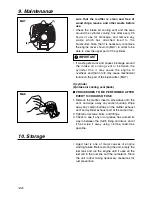
8. Operation
OP1
(1)
(2)
(3)
OP2
(4)
(5)
(6)
(4)
(5)
(6)
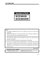
BCZ3000S
BCZ3000SW
OP3
OP4


