IDAC
Technical Support:
5
Possibility of setting a
press detection delay
.
Heartbeat
.
1.2
INSTALLATION
IDAC connects to the KNX bus through the on-board KNX connector. This device
requires an external 24V DC power supply.
Figure 1.
IDAC.
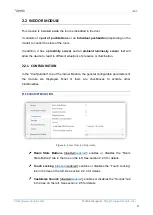
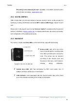
A short press on the
Prog. /Test button
(8) will make the device enter the
programming mode. The
Prog. /Test LED
(9) will then light in red. On the contrary, if
this button is held while the device gets connected to the bus, the device will enter the
safe mode
. In such case, the programming LED will blink in red colour.
For detailed information about the technical features of the device and about the
installation process, please refer to the corresponding
Datasheet
bundled with the
original package of the device and the installation manual available at
1.
Access LED indicator.
2.
Luminosity and proximity sensor.
3.
Touch area.
4.
NFC card reader.
5.
Tamper switch.
6.
15-pin connector.
7.
12-pin connector.
8.
Programming/Test button.
9.
Programming/Test LED.
10.
Interconnection cable (15-pin).
11.
Screws and metal plate for flush
mounting on door.
12.
Security screw.
13.
Touch areas.
14.
Luminosity and proximity sensor.
3
2
7
5
4
6
1
8
9
10
12
11
13
14
External view
Internal view


