Zenner 08765432 Скачать руководство пользователя страница 7

7

Installation instructions

Safety instructions

The installation has to be done by qualified per-
sonnel. Read the instructions carefully right up to 
the end before starting to mount the device.

The  current  laws  and  regulations  have  to  be 
observed, especially EN 1434 part 1+6, (in Ger-
many also AGFW directive FW202 and DIN 4713 
part 4 and the initial verification directive).
At  devices  with  communication  interfaces  or 
mains supply the general technical rules and the 
correspondent regulations have to be followed.

While demounting flow sensors and temperature 
sensors  make  sure  no  heating  water  escapes 
from the pipe – 

this can cause burns!

Close valves and release pressure before instal-
lation.

General Information  

Take care of:


the display must readable at all times,


to  avoid  malfunctions  due  to  other  interfer-
ences do not install fluorescent lamps, switch 
cabinets or electric devices such as motors or 
pumps  in  the  immediate  vicinity  of  the  meter 
(minimum distance 1 m),


all welding must be finished,


the  ambient  temperature  must  not  exceed 
55°C,


the  type  of  temperature  sensor  must  corre-
spond with the calculator,


the pulse value of the flow sensor must corre-
spond with the one from the calculator.

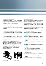
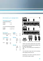
The  calculator  has  7  screwed  cable  glands  for 
wires with a diameter between 4,2 and 10 mm.
Keep unused glands closed.

Mind the connection order: temperature sensors 
first, flow sensor afterwards!

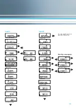
mulitdata is delivered ready for operation. It does 
not need any settings or adjustings.

Содержание 08765432

Страница 1: ...multidata Installation and operating manual Electronic energy calculator for heat meters with 2 inputs outputs optionally with M Bus RS 232 and RS 485 All that counts EnergyMetering...

Страница 2: ...EU The duration of initial verification validity in Ger many remains 5 years for heat meters After this period has expired the measuring device may no longer be used for billing in commercial use The...

Страница 3: ...or 5 Symbol Status Event Flow existent Attention Check system device for errors Data transmission Emergency operation Exchange device External power supply Code Error Event 1 Short circuit return sens...

Страница 4: ...ure sensor connection PT500 optional PT100 PT1000 Max cable length 2 wire 12 5 m PT500 2 5 m PT100 20 m PT1000 Max cable length 4 wire 20 m Interfaces optical optionally ZR Bus M Bus RS 232 remote rea...

Страница 5: ...ance approx 10 nF Input resistance approx 850 kOhm 100 Hz Version fmax 30 Hz Pulse duty factor 1 1 Input capacitance approx 2 5 nF Input resistance approx 850 kOhm fmax 1 Hz Pulse duty factor 1 1 to 1...

Страница 6: ...nds to the last position of the as sociated display value Example Output 1 energy output Energy display XXXXX XX MWh Last position 0 01 MWh 10 kWh Output pulse 10 KWh The calculator can be ordered wit...

Страница 7: ...lose valves and release pressure before instal lation General Information Take care of the display must readable at all times to avoid malfunctions due to other interfer ences do not install fluoresce...

Страница 8: ...e sensor cables are marked with colors red supply blue return Do not buckle extend or shorten the wires Do only use paired sensors with the same se rial number on it At 2 wire systems the cable length...

Страница 9: ...time can be checked in the display level 3 After having reached the date the battery has to be replaced if needed Operation test Check the calculator for any error codes in the display after installat...

Страница 10: ...TR 71 GND 72 Tx 73 Rx 74 RS 485 UB 71 GND 72 A 73 B 74 Switch Connection 2 wire Connection 4 wire If water meters with a potential free reed contact are connected to the inputs the connection can be m...

Страница 11: ...number Serial number input 1 Serial number input 2 Energy main display Cooling in change iover versions Volume Volume external input 1 Volume external input 2 Segment test Supply temperature Return t...

Страница 12: ...ated resp switches to the sub menu Hold down the button H un til the device switches to an other level or switches back from the sub menu Note Depending on your meter s model its displays can differ i...

Отзывы: