


Iron Man User Guide v. 1.4
7
3)
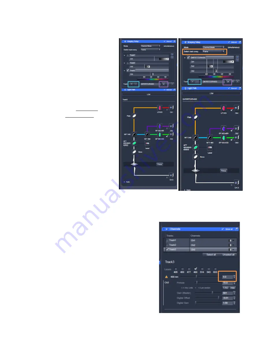
In the Imaging Setup window
– choose and set up the appropriate track(s) for your experiment.
-
You can
open a previous configuration
(little folder icon button at the bottom of the Imaging
Setup window) and edit this as
needed, you can reuse settings
from a previous .lsm file (open the
image and click on Reuse button
at the bottom of the Display
window), or you can set it up
yourself (advice at the end of this
guide).
-
Two major options – you can
image all fluorophores in multiple
channels on a single track or split
this into multiple tracks. Single
track will be faster, but may lead
to bleedthrough of your signal
across channels.
-
An example of both a single track,
multi-channel acquisition and
multi-track acquisition are shown.
-
To add or remove tracks, click the
“+” or “-“ buttons
next to Track.
-
If you will be imaging with
multiple tracks, set the “Switch
tracks every” option to
“frame”
to
avoid very slow imaging
4)
In the Channels window
- Make sure the correct lasers are
checked on for each track/channel you want to image. In
the example to the right, Track 3 utilizes the 488nm laser.
To adjust, select the channel above and check on or off the
appropriate lasers.
You can also adjust the laser intensity
% at this point.
For the Argon and Diode lasers, 3-5% is
usually sufficient, and for the HeNe lasers, 25-35% is
usually a good starting point.