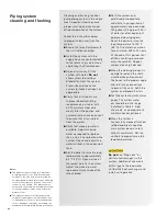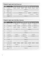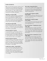
Troubleshooting
PCB System Error Codes
(Green LEDs)
Warning = FLASHING
Lock-out = STEADY
System
Error
Code
(COM
T Stat)
Fault Description
Potential Causes
LD1
LD2
LD3
LD4
OFF
OFF
OFF
X
Er 1
High pressure lockout
> 600 PSI
■
■
Low air flow (heating), low water flow (cooling)
■
■
Blower fan inoperable (heat mode)
■
■
Dirty air filter (heat mode)
■
■
Airflow by-passing air coil through due to poor sealing of
cabinet openings (heat mode)
■
■
Return air too hot (heat mode)
■
■
Air in risers (cool mode)
■
■
Dirty water strainer (cool mode)
■
■
Faulty zone valve (cool mode)
■
■
Mis-wired zone valve (cool mode)
■
■
Ball valves closed (cool mode)
■
■
Main water pump inoperable (cool mode)
■
■
Supply water too hot (cool mode)
OFF
OFF
X
OFF
Er 2
Low pressure lockout
< 40 PSI
■
■
Low refrigerant charge
■
■
Blower fan inoperable (cool mode)
■
■
Airflow by-passing air coil through due to poor sealing of
cabinet openings (cool mode)
■
■
Ball valves closed (heat mode)
■
■
Main water pump inoperable (heat mode)
OFF
OFF
X
X
Er 4
Freeze protection,
water side
■
■
Water temperature < 35°F or < 15°F (heating)
■
■
DIP switch 2 incorrectly set
■
■
Air in risers (heat mode)
■
■
Ball valves closed (heat mode)
■
■
Faulty zone valve (heat mode)
■
■
Main water pump inoperable (heat mode)
■
■
Dirty water strainer (heat mode)
■
■
Refrigerant charge quantity below factory recommendation
OFF
X
OFF
OFF
Er 5
Freeze protection,
air side, < 35°F
■
■
Blower failure (cooling)
■
■
Dirty air filter (cool mode)
■
■
Airflow by-passing air coil through due to poor sealing of
cabinet openings (cool mode)
■
■
Return air too cool (cool mode)
■
■
Refrigerant charge quantity above factory recommendation
OFF
X
OFF
X
Er 9,
Er 10
Condensate overflow
■
■
Clogged drain line
■
■
Condensate switch has residual water contacting from unit
installation/removal
OFF
X
X
X
Er 11
Over/under low voltage
protection
16VAC > voltage > 30VAC
■
■
Loss of power, brown-out
■
■
Main power voltage not within acceptable range
X
OFF
OFF
OFF
Er 13
LWT sensor failure
■
■
Sensor wiring not properly connected
■
■
Sensor resistance above or below specification
X
OFF
OFF
X
Er 14
DAT sensor failure
■
■
Sensor wiring not properly connected
■
■
Sensor resistance above or below specification
X
OFF
X
OFF
Er 15
FP1 sensor failure
■
■
Sensor wiring not properly connected
■
■
Sensor resistance above or below specification
X
OFF
X
X
Er 16
FP2 sensor failure
■
■
Sensor wiring not properly connected
■
■
Sensor resistance above or below specification
58


