Cooling
Ventilation
Filtering
Heating
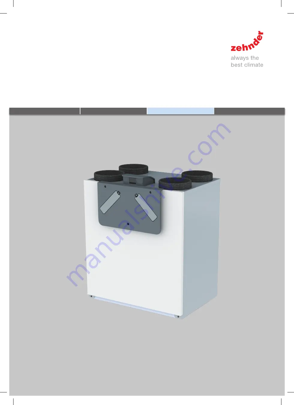
ComfoAir E350Manual for the service engineer
10001047667-0619-zw-zw-A4 ComfoAir E 350 GEN2 Service Zehnder-SI_EN.indd 1
11-07-19 13:30
Страница 1: ...Cooling Ventilation Filtering Heating ComfoAir E350 Manual for the service engineer 10001047667 0619 zw zw A4 ComfoAir E 350 GEN2 Service Zehnder SI_EN indd 1 11 07 19 13 30...
Страница 2: ...the display on the unit Information given in the Manual for the fitter Fitting conditions Information on transport and unpacking Commissioning procedures Installation procedures Available controls Ava...
Страница 3: ...ns 14 3 1 Service parts 16 3 2 Connection diagram 17 3 3 Dimension sketch 19 4 Maintenance procedures 20 4 1 Procedure for opening the unit 20 4 2 Maintenance of the casing 21 4 3 Maintenance of the h...
Страница 4: ...performance Installation commissioning and maintenance must be carried out by a certified person or company unless stated otherwise If this work is carried out by unauthorised persons it may result i...
Страница 5: ...the menu screen E Icon for activating the comfort temperature menu F Icon for activating the filter replacement menu G Icon for activating the error readout menu H Icon for activating the installer s...
Страница 6: ...TTING EXHAUST AIR TEMPERATURE LOW SETTING EXTRACT AIR TEMPERATURE FANS Readout SUPPLY AIR TEMPERATURE SUPPLY FAN RPM FIREPLACE MODE YES NO PREHEATER TEMPERATURE EXHAUST FAN RPM BALANCE SETTING SERVICE...
Страница 7: ...e heat exchanger are removed To prevent electrically charged parts being touched the power must still be manually disconnected from the unit after setting the SERVICE MODE Once the power is reconnecte...
Страница 8: ...for these valves Adjust the opened valves to the required air flow per room Measure the air flow again at each opened valve using a flow meter Check that the air flow complies with the standard for ea...
Страница 9: ...MENU RF SETTING ACTIVATION ON You now have 10 minutes to register the RF control Set METHOD on the display of the unit to DISCRETE CONTROL MENU SERVICE MENU RF SETTING METHOD DISCRETE CONTROL 4 6 sec...
Страница 10: ...ives the user enough time to purchase new filters before the dirty filters are to be replaced It is possible to set the alert to appear earlier by increasing the number of filter order days in the ser...
Страница 11: ...in frost conditions until deactivation 2 13 Explanation of ANALOGUE 0 10 V menu standard and RF SETTING optional The unit can be controlled with any analogue 0 10 V signal and or an RF signal To ensu...
Страница 12: ...ce ALTITUDE entered incorrectly Filters are dirty Heat exchanger is frozen 2 16 Explanation of RESTORE TO FACTORY SETTINGS menu The factory settings of the unit are permanently saved to the control PC...
Страница 13: ...al Geschwindigkeit Input signal 4 V Setting 1 Input signal between 4 V and 7 V Setting 2 Input signal 7 V Setting 3 What are the P VALUE and the I VALUE for PI Controller Proportional means that the d...
Страница 14: ...Polystyrene General Temperature range during transport and storage 20 C to 50 C Temperature range moved air 15 C to 50 C Temperature range of installation area 8 C is not a range Relative humidity of...
Страница 15: ...15 49 36 34 2 200 50 36 0 42 0 18 53 40 38 3 245 50 46 0 44 0 19 56 42 41 4 250 100 59 0 46 0 24 59 44 43 5 300 100 73 0 47 0 24 62 47 46 6 350 100 90 0 48 0 26 65 49 49 7 250 150 71 0 47 0 28 61 46 4...
Страница 16: ...0 control PCB with display 2 RF PCB RF receiver 3 Sensor upper section TEMP RH SENSOR 11 20 4 Filter set ISO Coarse ISO Coarse ISO Coarse ISO ePM1 according to ISO 16890 G4 G4 G4 F7 5 Bypass motor BYP...
Страница 17: ...S44 TEMP SENSOR 21 outdoor air n a C1 0 10 V input C2 Bathroom switch C3 n a C4 Malfunction dirty filter alert LED SAI Flash Output voltage at malfunction alert 5 V SA 0 3V E P N L M H 230V 50Hz Swit...
Страница 18: ...18 EN Front view of main PCB 10001047667 0619 zw zw A4 ComfoAir E 350 GEN2 Service Zehnder SI_EN indd 18 11 07 19 13 30...
Страница 19: ...elow view Side view Ma skizzen 10 NL 4 3 Maatschets 40 850 60 235 10 725 490 123 560 160 190 280 5 265 250 100 180 200 CA300 CA400 10 NL 4 3 Maatschets 40 850 60 280 10 725 490 123 560 160 190 280 5 2...
Страница 20: ...e electronics can be damaged by static charging so always take measures to prevent electrostatic discharge e g antistatic belt when handling the electronics Zehnder recommends hiring a specialist clea...
Страница 21: ...it to the service mode Disconnect the power to the unit Remove the 3 screws from the front cover Remove the front cover Remove the heat exchanger Pull on the strap of the heat exchanger Do not cut the...
Страница 22: ...back Press temperature sensor T21 up out of the insulation cover next to the bypass flap While holding the clamp away from the flap pull the flap towards you During installation Place the Zehnder log...
Страница 23: ...eed as follows 1 1 2 2 3 Remove the bypass flap according to the instructions in the corresponding section Set the unit to the service mode Disconnect the power to the unit Remove the 3 screws from th...
Страница 24: ...the front cover Remove the front cover Remove the 3 screws from the display cover Then remove this cover Remove the 4 screws from the electronics cover Then remove this cover 4 5 6 Pull the black con...
Страница 25: ...Contamination dirt and grease Air leakages loose connections Resistance bends dents and blocked valves Valves Resolve any problems detected 4 9 Procedure for completing maintenance 1 2 3 Example repor...
Страница 26: ...ribes how to solve all error codes 5 1 Malfunction alerts on the display of the unit Code Meaning BYPASS MOTOR 11 ERROR Malfunctions in the motor of the bypass valve on the extract air side BYPASS MOT...
Страница 27: ...nit Remove the 3 front cover screws Remove the 3 screws from the display cover Then remove the cover Remove the 4 screws from the electronics cover Then remove the cover Pull the black connector of th...
Страница 28: ...is located on the right 4 5 6 Remove the heat exchanger Pull on the strap of the heat exchanger Do not cut the strap The strap is necessary to pull out the heat exchanger from the unit You can only r...
Страница 29: ...pressure sensor Then pull the sensor sideways from the sensor container 5 6 Resetting errors Most errors will automatically reset themselves once the problem has been resolved The following errors can...
Страница 30: ...rol PCB 2 Go to the next question 2 Are all connectors properly connected to the control PCB See connection diagram in the Section Technical specifications Yes 1 Inspect the fans as described in the m...
Страница 31: ...nd in the malfunction Section Access to the T11 T20 sensor 2 Go to the next question No 1 Connect everything as described in the connection diagram in the section Technical specifications 2 Follow the...
Страница 32: ...22 ERROR Malfunctions in the temperature sensor for the exhaust air outdoor air downstream of the preheater For the right hand unit TEMP SENSOR 12 and 21 are to the centre left of the unit For the le...
Страница 33: ...the control PCB 4 Replace the control PCB as described in the manual supplied 5 Follow the procedure for completing the maintenance No 1 Get the service set for the control PCB 2 Replace the control...
Страница 34: ...escribed in the section Access to the control PCB 2 Go to the next question No 1 Place temperature sensor T21 properly in the insulation cover beside the bypass valve How to get access to this sensor...
Страница 35: ...tem test of the unit as described in the section Carrying out a system test 2 Does the unit have an error Yes Solve the error as described in the relevant malfunction table No Go to the next question...
Страница 36: ...a BYPASS MOTOR 11 ERROR or BYPASS MOTOR 20 ERROR Yes Solve the error as per the relevant resolution table No Go to the next question 3 Has it been cold for an extended period Yes The unit thinks that...
Страница 37: ...bathroom control has finished This takes no more than half an hour No Go to the next question 2 Are the settings of the RF input programmed as per the specifications of the controls See the manual fo...
Страница 38: ...10001047667 0619 zw zw A4 ComfoAir E 350 GEN2 Service Zehnder SI_EN indd 38 11 07 19 13 31...
Страница 39: ...10001047667 0619 zw zw A4 ComfoAir E 350 GEN2 Service Zehnder SI_EN indd 39 11 07 19 13 31...
Страница 40: ...77933 Lahr Germany T 49 78 21 586 392 F 49 78 21 586 406 sales international zehndergroup com www international zehnder systems com ZGNL Manual_10001047667 V0719 EN Subject to change 10001047667 0619...