

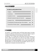


RESERATOR 1 V2
10
※
The specifications of any product may change without prior notice to improve performance.
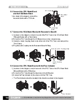
5. 6 Connect the CPU Water Block
and the VGA Water Block
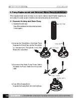
1) As shown in the diagram, connect the
two water blocks with a PVC tube.
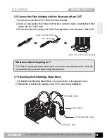
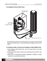
5. 7 Connect the VGA Water Block with Reserator’s Base IN
1) As shown in the diagram, connect one end of the PVC Tube to the VGA Water Block
Fitting and fasten with a Tube Clamp.
2) Pull out the PVC Tube through the I/O Bracket hole on the computer case.
3) Connect a Quick Coupling Insert to the other end of the PVC Tube and clamp with a
Tube Clamp.
4) Plug the Quick Coupling into the Reserator’s Base IN fitting.
5. 8 Connect the CPU Water Block with the Flow Indicator
1) As shown in the diagram, connect one end of the PVC Tube to the CPU Water Block
fitting and fasten with a Fitting Cap.
2) Pull out the PVC Tube through the tube hole on the I/O Bracket.
3) Connect the Flow Indicator on the other end of the PVC Tube.
※
The Flow Indicator should be installed in the direction as shown in the diagram.
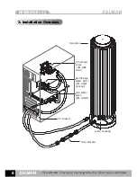
PVC Tube
CPU Water
Block
VGA Water
Block
I/O Bracket
Quick Coupling
Insert
Base IN Quick Coupling Body
Flow Indicator
Содержание RESERATOR1 V2
Страница 18: ......


