background image

17               

ZABER TECHNOLOGIES INC.

Getting Started Guide

While complete information on general usage of the Oscilloscope 
tool can be found at 

www.zaber.com/Oscilloscope

, here are some 

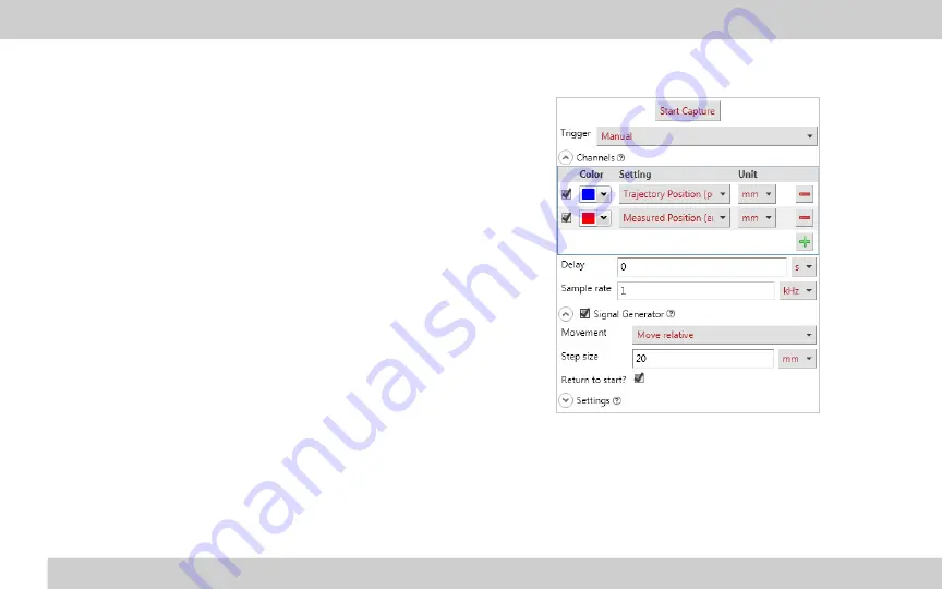
recommended settings to use for plotting the step response of a 
servo device:

Trigger

 – Select Manual mode to capture high resolution information 

over a limited time period. Automatic mode will capture lower 

resolution information indefinitely. 

Channels

 – Select the Trajectory Position (pos setting) and 

Measured Position (encoder.pos setting) to compare the expected 
and actual trajectories. Choose ‘mm’ from the Unit selector. 

Sample Rate

 –The maximum sample rate depends on the Trigger 

type. For Manual mode, selecting a higher frequency will give a 
smaller sample period. Enter 1 kHz for a reasonable mix of 
resolution and period for capturing a movement. 

Signal Generator

 – Enable this to create a movement during the data 

capture. We recommend a relative movement with a step of 20 mm 
as a sample movement, and resetting after the capture is complete.

Содержание X Series

Страница 1: ...Simplifying Motion Control www zaber com ZABER TECHNOLOGIES X Series Device Getting Started Guide ...

Страница 2: ...ONFIGURE 7 Zaber Console 7 COM Ports 7 Renumber 8 Peripheral IDs 8 Protocol 9 Contents VERSION 2 0 PDF download www zaber com XSeriesGettingStarted pdf CONTROL 9 Software 9 Zaber Console 9 Programming Libraries 10 Resolution Stepper Servo Motors 10 I Os Triggers 12 Servo Device Tuning 12 Manual Knobs 18 Joystick 19 TROUBLESHOOTING 21 Firmware Update 21 Slipping and Stalling 21 Resetting to Factory...

Страница 3: ...smoke are not expected during normal operation if encountered discontinue operation and contact Customer Support 3 To reduce the risk of electrostatic damage avoid touching the electrical contacts of the data cables included with your device s 4 Before storing your device s retract any extended components in order to keep them clean and to protect them from damage 5 Do not expose device s to vibra...

Страница 4: ...30 days of the purchase date for a refund less applicable shipping costs High vacuum 10 6 Torr devices cannot be returned for refund once they have been removed from their sealed packaging All standard products are warrantied against defects in manufacture and design for one full year from the purchase date This warranty excludes products that have been misused modified or disassembled by the cust...

Страница 5: ...common features such as connectors protocols and power The series is indicated by the first letter of the device s name For example the X LSM025A model belongs to the X Series family This guide specifically relates to X Series devices See an older version of the manual for setup instructions for T Series or A Series devices at www zaber com GettingStarted pdf Closed Loop and Servo Devices For Zabe...

Страница 6: ...clude guards such as plates inserts covers or fasteners which prevent movement of devices during shipping and limit potential damage from shock loads If they are present for a device they will either be clearly visible and intuitive to remove or clearly marked with labels and instructions Following those instructions remove any such components before powering the device Read the manual online for ...

Страница 7: ...vices can be daisy chained using an M8 cable such as the X DC02 Drivers may be required if COM port does not appear Download and installation instructions here www zaber com software Drivers are required Download link and installation instructions can be found here www zaber com USB Connect Peripherals if applicable If using a stand alone controller plug it into the motorized axis Depending on the...

Страница 8: ...draw of the devices and the current capacity of the power supply Connect USB Connect the first controller built into the device or stand alone to your computer via USB using the cables included if you ordered an accessory kit X Series devices can connect to a computer s USB port with an X USBDC cable Stand alone controllers also have the option to connect directly to a computer s USB port with a U...

Страница 9: ...n sections are based on Zaber Console Please contact Customer Support if you would like to use any other software More information about Zaber Console and other software options is included in the Control section page 9 of this guide COM Ports A COM port is a specific serial connection on a computer such as COM1 or COM3 When connected via USB your computer should create a virtual COM port that wil...

Страница 10: ...rs such that the one connected to the computer is device 1 the next in the chain is device 2 and so on ZABER COM VSR20A T3 SN 12333 PID 44456 Product name Scannable QR code directs to Quick Set up page www zaber com QuickSetup Peripheral or device ID Serial number Peripheral IDs Stand alone Zaber controllers are designed to work easily with Zaber peripherals Peripherals with the Auto Detect featur...

Страница 11: ...onnected to a computer you are ready to start controlling it To begin communicating with your device you will need to select a software interface The following sections outline some of the software options available to you Zaber Console Zaber Console is free open source software that is designed for ease of use Zaber Console allows you to manage port communication identify devices send commands to...

Страница 12: ...istance corresponding to this increment depends on the type of motor that drives the device For devices driven by stepper motors an increment is a microstep of the motor and the size of an increment is the device s Microstep Size specification For servo devices an increment is an encoder count and the size of an increment is the device s Encoder Resolution specification Microstepping Stepper motor...

Страница 13: ...itioning Zaber s servo devices feature a variety of digital and analog position encoders for feedback An encoder count is the smallest movement of the encoder that will be registered by the controller Speed and Acceleration While microsteps for stepper motor devices or encoder counts for direct drive devices are the increments of position on Zaber devices there are conversion factors required to c...

Страница 14: ... Use caution when adjusting parameters it s possible to enter values that will cause the device to become unstable and move erratically If this occurs press the Disable Driver button to stop current to the motor and stop driven motion The parameters can then be adjusted to be more stable or returned to default values Press Enable Driver to resume driven motion I Os Triggers Some Zaber controllers ...

Страница 15: ...nd will be displayed as long as that file is selected Use this tool to move parameter sets from computer to computer or to easily apply parameter sets to multiple devices Tuning Methods The servo tuning tool includes 4 modes for tuning Simple The inertia of the moving load is the minimum information about an application required to choose reasonable tuning parameters For linear motion this is the ...

Страница 16: ...a input when using Simple tuning cannot be re calculated based on low level parameters In addition to the writable presets there is also a default preset which contains the factory tuning values The default preset can be read or applied but cannot be overwritten Restore the defaults at any time to apply safe but not necessarily optimized parameters Advanced Servo devices may have different control...

Страница 17: ...R TECHNOLOGIES INC Getting Started Guide Step 1 Choose a tuning method Step 2 Enter values Step 3 Select a Preset to save the values to and press Write Step 4 Select the Preset to make Live and press Activate ...

Страница 18: ...es over time A variety of information can be read such as the expected position based on the trajectory planner the actual position based on encoder feedback and the temperature of the motor or driver Plotting the first two the expected and measured positions during a movement can be useful in assessing the effectiveness of different servo tuning parameters it can show performance such as rise tim...

Страница 19: ...definitely Channels Select the Trajectory Position pos setting and Measured Position encoder pos setting to compare the expected and actual trajectories Choose mm from the Unit selector Sample Rate The maximum sample rate depends on the Trigger type For Manual mode selecting a higher frequency will give a smaller sample period Enter 1 kHz for a reasonable mix of resolution and period for capturing...

Страница 20: ... the end of the movement cloop settle tolerance and cloop settle period settings See the online product manual for more information on these settings Manual Knobs Most Zaber devices include a manual knob for moving the unit without a computer connection Devices still need to be connected to a power source for the manual knob to work Indexed Knob Functionality Turning the knob Moves the device base...

Страница 21: ...ticks are not intended to act as controllers so each axis will still require an integrated controller or a stand alone controller Default Key Configuration for X JOY3 Key Short Press Long Press 1 Stop Home 2 Send alerts 1 2 Send alerts 1 3 4 3 Move to saved position Save position 4 Move to saved position Save position 5 Move to saved position Save position 6 Axis 1 low speed Axis 1 high speed 7 Ax...

Страница 22: ...Instructions Connect The joystick must be connected to a computer to configure it Once it is configured you can operate it with or without a computer connection The joystick should be the first device in the daisy chain Once all devices are connected to the chain send the renumber command to all device The joystick will be device 1 and the joystick will control devices 2 3 and 4 the three devices ...

Страница 23: ...tioner is likely slipping or stalling If the positioner is slipping or stalling and it has encoders the blue LED on the controller will also flash To correct the problem try the following steps 1 Lower the maximum speed setting 2 Lower the maximum acceleration setting 3 Reduce the load on the positioner If the positioner continues to stall with no external load at default speed and acceleration se...

Страница 24: ...checksum mismatch Blinking Moving under manual control Fading in and out Peripheral plugged in and requires activation Blue On Peripheral is deactivated Flashing Device is slipping Blinking at 0 5 Hz Device has stalled and stopped Blinking at 2 Hz Driver is diabled see warning flags for explanation 2 flash burst at 1 Hz Stationary device was forced out of position 5 flash burst at 0 5 Hz Encoder h...

Страница 25: ...23 ZABER TECHNOLOGIES INC Getting Started Guide Customer Support 1 888 276 8033 Toll Free Canada USA 1 604 569 3780 Direct contact zaber com ...

Отзывы: