


Product
ZX
Date:
2018.09.19
Page:
33 of 62
Z-Laser Optoelektronik GmbH
Merzhauser Str. 134
D-79100 Freiburg
Tel.: (0761)29644-44
Fax: (0761)29644-55/56
Operation manual
Document-ID: UI-ZL-140011-0.9-2018-09-19
0.9
Author:
CSCH
Merzhauser Str. 134 ~ 79100 Freiburg ~ Tel.: +49-(0)761-29644-44 ~ Fax: +49-(0)761-29644-55
www.z-laser.com
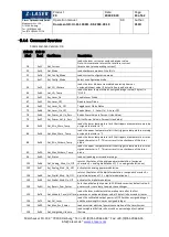
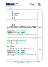
3.4.7
List of write telegrams
Command-Set-Version: 0.3
Feature
Reference
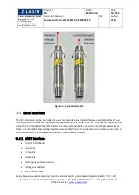
SET_CONFIG_MODE -
selects a configuration for the connector pins. If a device is set
to a configuration mode without an active communication interface the following
sequence has to be sent repeatedly during start up to switch to a new configuration
mode:
Set_User_Password (0xF5)
Set_Configuration_Mode (0x17)
As soon as you get a valid answer for both commands, the new configuration mode is
active.
Digital Modulation Input:
PWM input , TTL
Analog Modulation Input:
analog power input
Fail Output:
Active low signal that statically indicates all detected error conditions
Fail Input:
Sets the ZX into failure state. The laser is switched off. A power cycle is
required to leave this failure state.
SCL
: Serial Clock Line of TWI interface
SDA:
Serial Data Line of TWI interface
TX:
Transmit Data of UART interface
RX:
Receive Data of UART interface
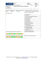
Config. Modes:
User PW
protected
0x00
Modulation_Fail_Out
Pin 1: VCC
Pin 2: Digital Modulation Input
Pin 3: GND
Pin 4: Analog Modulation Input
Pin 5: Fail Output
0x01
N/A
0x02
UART_Com_Dig_In
Pin 1: VCC
Pin 2: Digital Modulation Input
Pin 3: GND
Pin 4: RX
Pin 5: TX
0x03
TWI_Com_Dig_In
Pin 1: VCC
Pin 2: Digital Modulation Input
Pin 3: GND
Pin 4: SCL
Pin 5: SDA
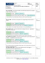
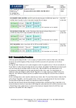
WR-Device-ID CMD (0x17)
Config. Mode
Lo-Byte CRC
RD-Device-ID Status Byte
Hi-Byte CRC
Hi-Byte CRC
(RD transmission can be repeated)
Lo-Byte CRC