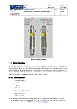
z-laser ZX Series Скачать руководство пользователя страница 20


Product 

ZX


Date: 

2018.09.19


Page: 

20 of 62 

Z-Laser Optoelektronik GmbH


Merzhauser Str. 134 

D-79100 Freiburg 
Tel.: (0761)29644-44 

Fax: (0761)29644-55/56


Operation manual 

Document-ID: UI-ZL-140011-0.9-2018-09-19


0.9 

Author: 

CSCH


Merzhauser Str. 134 ~ 79100 Freiburg ~ Tel.: +49-(0)761-29644-44 ~ Fax: +49-(0)761-29644-55 

[email protected] ~ 

www.z-laser.com


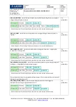
The ASCII representation of the UART-frames is identical to the hexadecimal representation of the 

TWI-frames. Even the device-ID must be transmitted when UART is used; see light green telegram 

byte for TWI transmissions below. So the given documentation refers to TWI but is valid for UART 

communication as well. 


Example: 

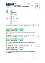
Documentation of the TWI telegram that reads the ZX Firmware Version 


The corresponding TWI telegram in 

hexadecimal 

representation: 

TWI write frame ->  


88 F0 0E EF                    


length: 4 Bytes 

TWI read frame ->  


00 03 00 05 8D 35             


length: 6 Bytes 


The corresponding UART telegram in 

ASCII 

representation: 

UART request telegram -> 

 88F00EEF<LF>   


length: 9 Bytes 

UART receive telegram->  

000300058D35<LF> 


length: 13 Bytes 


The length of the UART frame is always calculated as: (length of TWI frame) * 2 + termination 

character. 


CRC (CCIT format) is calculated from the command and data frame without the TWI-address. See 

details in next subchapter. 
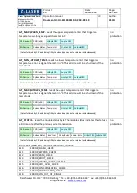
3.4.2


TWI Interface 


The TWI communication interface is operated via SCL and SDA (Pin 4 and Pin 5) according to 

standardized physical TWI protocol definition up to 100 Kbit/s. No pull-up resistors are implemented 

for both wires; this must be done on the host side. A proper GND reference of the applied signals has 

to be ensured. Signal-GND (Pin 3) can be used for this. 

Please refer to the original Philips specification that can be found at this URL: 


http://cache.nxp.com/documents/user_manual/UM10204.pdf 


NOTE 

Please pay attention to the following deviations from the original 

Philips I²C specification: 


Max high level output voltage 3.3V  


1 mA current sink capacity 


Pull-Up resistors must be chosen in accordance with the current 

sink specification 

WR-Device-ID  CMD (0xF0) 

RD-Device-ID  System Status 


Major Version  Minor Version 

Build 

Hi-Byte CRC


Lo-Byte CRC


Hi-Byte CRC


Lo-Byte CRC


Содержание ZX Series

Страница 1: ...ADVANCED INFORMATION Laser Operator s Manual ZX...

Страница 2: ...hapter Create a serial connection added 0 4 17 07 19 CSCH General amendments 0 5 17 08 19 CSCH General amendments 0 6 AS Corrected CMD ID of SET_POWER_VALUE_IN_PERC 0 7 17 11 20 CSCH General amendment...

Страница 3: ...ng 16 Power supply 18 Focus adjustment 18 Serial Interface 19 3 4 1 UART Interface 19 3 4 2 TWI Interface 20 3 4 3 Create a serial connection 22 3 4 4 Command Overview 24 3 4 5 System Status Byte 25 3...

Страница 4: ...Button 49 5 8 3 Digital Modulation 49 Configuration Mode Select Section 50 5 9 1 Configuration Modes Select Control 50 5 9 2 Configuration Mode Description 50 5 9 3 Set Selected To Default Button 50...

Страница 5: ...18 09 19 0 9 Author CSCH Merzhauser Str 134 79100 Freiburg Tel 49 0 761 29644 44 Fax 49 0 761 29644 55 info z laser de www z laser com ZX20 F focusable 56 ZXS20 separated electronics fixed focus 57 ZX...

Страница 6: ...following instructions to learn how to use and operate the ZX laser module as intended CAUTION NOTE Before initial commissioning please read the entire manual Operating the product in a manner not sp...

Страница 7: ...omogeneous DOE dot circular elliptical line Gaussian homogeneous DOE dot circular elliptical line Gaussian homogeneous DOE dot circular elliptical Focusability optional F none optional F Modulation Fr...

Страница 8: ...o your shipping company After unpacking please carefully check the laser product for potential damage If you discover any damage please report immediately to Z LASER In the case of physical damage do...

Страница 9: ...Particular attention has to be paid to the correct electrical connection Please see chapter 3 1 Electrical interfaces Pinning for appropriate instructions Please contact the Z LASER service department...

Страница 10: ...I ZL 140011 0 9 2018 09 19 0 9 Author CSCH Merzhauser Str 134 79100 Freiburg Tel 49 0 761 29644 44 Fax 49 0 761 29644 55 info z laser de www z laser com NOTE The laser driver unit LDU will stop laser...

Страница 11: ...of optical instruments with this product will increase eye hazard Do not shine laser in the direction of other people or at reflective surfaces that might cause exposure to the human eye The laser ra...

Страница 12: ...gned for looking directly at a laser beam Checks Check the power output of the laser frequently with an appropriate power meter especially before beginning the procedure Appropriate eyewear should be...

Страница 13: ...quired information as described in the ANSI Z136 1 standard and will be removed when the laser is not in use Fire Hazards Class 4 laser systems represent a fire hazard Enclosure of Class 4 laser beams...

Страница 14: ...er Klassen 2 f r Unterrichtszwecke 3R 3B oder 4 bei Nichtbenutzung gegen unbefugten Gebrauch durch das Abnehmen des Schl ssels des Schl sselschalters gesichert sind 8 Abs 4 Lasereinrichtungen der Klas...

Страница 15: ...ot specified in this document may lead to safety hazards and will void the product warranty CAUTION NOTE Laser emission of this product can cause serious damage to the human eye Before operate the pro...

Страница 16: ...ted by a 5 Pin M12 connector with A Coding or a 6 pin cable with open leads The factory set default pin assignment is shown in Table 3 While Pin 1 and Pin 3 are fixed and unchangeable Pin 2 Pin 4 and...

Страница 17: ...smission error is caused by turn on delays of the laser diode 06 07 Fail Out 3 3V CMOS output active low Signal pulled to GND if an error is present 3 ALL GND Common ground System Ground please ensure...

Страница 18: ...ty and transient over voltages There is no ON switch and shutter Once supply voltage is applied the module starts powering up During start up procedure self testing routines verify the safety architec...

Страница 19: ...s being transmitted via a serial interface Two transmission standards are supported on dedicated IO Pins UART and TWI The user can operate one of each at a time When the TWI interface is used external...

Страница 20: ...F length 9 Bytes UART receive telegram 000300058D35 LF length 13 Bytes The length of the UART frame is always calculated as length of TWI frame 2 termination character CRC CCIT format is calculated fr...

Страница 21: ...icates the success of the transmitted write telegram For write telegrams the read transmission can be repeated multiple times until the status indicates a successful completion of the command processi...

Страница 22: ...Interface GUI provided by Z LASER But you can also use a standard command line interface to create a serial connection For modules that are already in a Configuration Mode that allows serial communica...

Страница 23: ...Sequence UART TX Set User Password 88 f5 55 73 65 72 ef 21 LF Addr CmdID Password CRC16 Linefeed TX Set User Password 88 f5 55 73 65 72 ef 21 LF switch power supply on TX Set User Password 88 f5 55 7...

Страница 24: ...aracter in C 86 0x56 Get_Max_Warn_Temp reads the upper temperature limit that triggers a temperature warning as signed character in C 88 0x58 Get_Min_Shtdwn_Temp reads the lower temperature limit that...

Страница 25: ...7 Set_Default_Pow_Val save the current power value as startup default 252 0xFC Get_TWI_Addr reads the TWI Address of the device for serial communication 253 0xFD Set_TWI_Addr writes the TWI Address of...

Страница 26: ...2 Enable on off the analog modulation control input 1 on Effective only in configuration modes with analog modulation Bit 3 Reserved for future use Bit 4 Enable on off the fail out signal 1 on Effecti...

Страница 27: ...temperature limit that triggers a temperature warning as signed character in C no protection WR Device ID CMD 0x22 RD Device ID System Status Hours HiByte Hours LoByte Status followed by CRC and trail...

Страница 28: ...n Error Codes MSB first can t be reset during runtime no protection Bit 0 ERROR_FLASH_CHECK Bit 1 ERROR_EEPROM_CHECK Bit 2 ERROR_RAM_CHECK Bit 3 ERROR_BOOT_CHECK Bit 4 ERROR_WRONG_INPUT_VOLTAGE Bit 5...

Страница 29: ...ERPOLATION_TABLE Bit 25 ERROR_SMCU_CALIBRATION Bit 26 ERROR_PERIPHERAL_CHECK Bit 27 ERROR_CMD_EXECUTION Bit 28 ERROR_BYPASS_TRANSISTOR Warning Codes Bit 0 WARNING_LD_NTC_PROBLEM Bit 1 WARNING_LD_OVERT...

Страница 30: ...IFETIME reads weigthed lifetime in hours and as percentage of estimated lifetime no protection WR Device ID CMD 0x68 Hi Byte CRC Lo Byte CRC RD Device ID System Status Hi Byte CRC DIgital Mod Status f...

Страница 31: ...hen data can not be returned instantaneously Hi Byte CRC Lo Byte CRC Hi Byte CRC Lo Byte CRC ASCII Digit 0 Digi 0x01 WR Device ID CMD 0xA6 RD Device ID System Status Power Value Hi Status followed by...

Страница 32: ...ESS reads the TWI Address of the device for serial communication no protection WR Device ID CMD 0xF2 RD Device ID System Status ASCII Digit 9 Status followed by CRC and trailing fill bytes when data c...

Страница 33: ...e new configuration mode is active Digital Modulation Input PWM input TTL Analog Modulation Input analog power input Fail Output Active low signal that statically indicates all detected error conditio...

Страница 34: ...cannot be stored permanently it will turn back to the default value after the next power cycle no protection SET_LASER_OFF deactivates the laser emitting In case of activated analog or digital modulat...

Страница 35: ...programs the upper temperature limit that triggers a temperature warning as signed character in C User PW protected SET_ANALOG_MOD_ON_OFF programs the status of the analog power modulation unsigned ch...

Страница 36: ...on multiple times until the busy flag indicates the completion Bit 0 0 All subsequent TWI telegrams are discarded before the busy bit is reset The returned status indicates a discarded telegram with a...

Страница 37: ...ciple The laser power cannot be adjusted directly since there is no calibrated measurement implemented for the laser power out of the laser diode Instead the laser power is controlled by adjusting the...

Страница 38: ...ser off Warning Blink Code n laser off Laser is ready to emit One or more warnings pending The number of green blinking pulses corresponds with warning code If there are more than one warning pending...

Страница 39: ...or code If there are more than one error pending only the first that occurred is displayed Error Blink Codes 1 Not Used 2 over under temperature shutdown 3 wrong Vin voltage 4 internal error 5 interna...

Страница 40: ...y The voltage supply for the MMCU can be shut down by the SMCU The surveillance MCU SMCU operates from independent supply voltage VCC_S which is derived from the primary power supply It supervises cri...

Страница 41: ...s every 10 milliseconds to each other After 10 missing tokens either MCU assumes that the counterpart is unavailable and shuts down the entire system ERROR Bit 13 Independent methods of laser power sh...

Страница 42: ...cation between a laser module and a PC via UART connection This software helps you to understand the principal communication with a ZX module and allows you to control and configure it Supported Opera...

Страница 43: ...11 0 9 2018 09 19 0 9 Author CSCH Merzhauser Str 134 79100 Freiburg Tel 49 0 761 29644 44 Fax 49 0 761 29644 55 info z laser de www z laser com 4 The following window gives you a summary of the parts...

Страница 44: ...ZX module with your PC and start Z Remote see 3 1 2 Use the pull down menus in the interface section to select the communication protocol e g UART and the corresponding COM Port assigned to the ZX mo...

Страница 45: ...644 44 Fax 0761 29644 55 56 Operation manual Document ID UI ZL 140011 0 9 2018 09 19 0 9 Author CSCH Merzhauser Str 134 79100 Freiburg Tel 49 0 761 29644 44 Fax 49 0 761 29644 55 info z laser de www z...

Страница 46: ...4 79100 Freiburg Tel 49 0 761 29644 44 Fax 49 0 761 29644 55 info z laser de www z laser com Control elements of remote section 5 5 1 Interface Use both controls to select a communication protocol and...

Страница 47: ...com 5 5 4 Connect Button Use this button to connect disconnect the laser module 5 5 5 Optical Power Control This item controls the optical output power You can enter a new value by writing it into the...

Страница 48: ...cator This display indicates the nominal optical output power mW with the power control set to 100 5 6 3 Item Number Indicator This display indicates the Item Number of the connected ZX module 5 6 4 S...

Страница 49: ...tes the weighted lifetime related reliability Modulation Section This section indicates and describes and controls the laser modulation 5 8 1 Modulation Indicator This display indicates and describes...

Страница 50: ...onfiguration Mode Select Section 5 9 1 Configuration Modes Select Control Use this control to select one of the available Configuration Modes 5 9 2 Configuration Mode Description This item shows the p...

Страница 51: ...build all available commands manually This Wizard can help you to develop own communication interfaces for ZX modules It gives you a short description of every byte used in command or receive frames T...

Страница 52: ...5 Byte Descriptions Send Section Short descriptions for every data byte 5 11 6 Select Buttons Send Section You can assign every single data byte to the Multi Slider by pressing the corresponding Selec...

Страница 53: ...icator Signaling ZX warnings decoded in status byte of response command 5 11 12 Error Warning Description Short description of errors and warnings decoded in status byte 5 11 13 Receive Data Bytes Rec...

Страница 54: ...acking Tab 5 12 1 Start Button laser diode current section This button activates the tracking of the laser diode current Toggle this button to reset the corresponding diagram 5 12 2 Laser Diode Curren...

Страница 55: ...1 29644 44 Fax 0761 29644 55 56 Operation manual Document ID UI ZL 140011 0 9 2018 09 19 0 9 Author CSCH Merzhauser Str 134 79100 Freiburg Tel 49 0 761 29644 44 Fax 49 0 761 29644 55 info z laser de w...

Страница 56: ...1 29644 44 Fax 0761 29644 55 56 Operation manual Document ID UI ZL 140011 0 9 2018 09 19 0 9 Author CSCH Merzhauser Str 134 79100 Freiburg Tel 49 0 761 29644 44 Fax 49 0 761 29644 55 info z laser de w...

Страница 57: ...n manual Document ID UI ZL 140011 0 9 2018 09 19 0 9 Author CSCH Merzhauser Str 134 79100 Freiburg Tel 49 0 761 29644 44 Fax 49 0 761 29644 55 info z laser de www z laser com ZXS20 separated electroni...

Страница 58: ...Product Labelling The ZX laser module is labelled with a nameplate and a laser class sticker If one of these labels is missing do not operate the laser Nameplate example The ZX nameplate contains the...

Страница 59: ...ipped with enough headroom for an operating time of at least 10 000 hours Z Laser can guarantee a MTTF of at least 10 000 hours for the ZX laser module when operated within the specified temperature l...

Страница 60: ...n manual Document ID UI ZL 140011 0 9 2018 09 19 0 9 Author CSCH Merzhauser Str 134 79100 Freiburg Tel 49 0 761 29644 44 Fax 49 0 761 29644 55 info z laser de www z laser com 11 Disposal The ZX laser...

Страница 61: ...2 Declaration of Conformity Conformity to EMC standards refers only to complete ZX modules and does not include customer cabling Name Product ZX ZX meets the requirements of the directives 2014 30 EU...

Страница 62: ...ital Converter DAC Digital to Analog Converter CW Continuous wave GUI Graphical user interface represented by the Z Remote Software LCByp Laser Current Bypass safety switch to test the system integrit...

Отзывы: