7
ELECTRIC FURNACE INSTALLATION
These Installation procedures are suggested for typical
electric furnace installations. Since all installations are
different from each other, the sequence of these steps may
differ from the actual installation.
Only qualified hVAC
technicians should install this furnace
.
The B5BV series electric furnace is shipped ready for
vertical upflow installation and is approved for attic,
basement, alcove/closet or crawlspace installation with
zero clearance to combustibles. See Figure 1 (page 4)
for required installation clearances.
This appliance is
only for indoor use.
• Remove the shipping crate and User’s Manual from the
equipment.
• The unit must be leveled at installation and attached to
a properly installed duct system.
• The surface that the electric furnace is mounted on
must provide sound physical support of the unit.
• The electric furnace must be installed so that all electrical
components are protected from water.
• If a louvered door is installed across the front of this
unit, the appliance must be mounted flush or behind
front edge of finished wall.
Upflow Installations
All electric furnaces are factory shipped, ready for upflow
installation. All return air must enter from the bottom of the
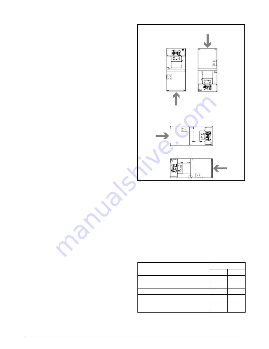
unit when installed in the upflow configuration. A typical
upflow unit is shown in Figure 3.
Position the electric furnace on top of the return air duct
and secure together with sheet metal screws. The screws
must penetrate the sheet metal cabinet and duct. Tape or
seal all seams if required by local code.
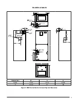
To attach the supply air duct to the electric furnace, bend
the perforated flanges (Figure 5, page 8) upward 90° with
a pair of wide duct pliers. Position the duct on top of the
electric furnace and secure together with sheet metal
screws. Make sure the screws penetrate the sheet metal
casing and flanges. Tape or seal all seams if required by
local code.
NOTE:
If an upflow pedestal mounting stand is fabricated
in the field, the stand must be constructed strong
enough to support the unit with all accessories installed
(approximately 130 lbs. for B-cabinet models and 200 lbs.
for C-cabinet models). The construction of the pedestal
stand must also allow for at least 235 in
2
free opening (300
in
2
for C-cabinet models) in the application. Field fabricated
upflow pedestal mounting stands must be constructed of
noncombustible materials. Position the electric furnace
on top of the mounting stand and secure together with
sheet metal screws. The screws must penetrate the sheet
metal cabinet and duct. Tape or seal all seams if required
by local code.
Downflow Installations
B5BV electric furnaces can be converted to downflow
operation by flipping an upflow unit 180°. A typical
installation of the unit in a downflow application is shown
in Figure 3.
NOTE:
Downflow installations require the use of a plenum
connector (or its equivalent) if the supply air ducts pass
through the floor of the structure. This factory supplied
accessory must be installed in the floor cavity and attached
to the supply air duct before the downflow unit is installed.
Available plenum connectors for all B5BV electric furnaces
are listed in Table 1. All return air in downflow applications
must enter through the top of the unit.
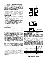
Figure 3. Installation Configurations
Return
Air
Return
Air
UPFLOW
DOWNFLOW
Return
Air
HORIZONTAL RIGHT
Return
Air
HORIZONTAL LEFT
Table 1. Optional Accessory Kits
Description
Cabinet Size
B
C
Downflow Plenum Connector, 6.25”
913840 914969
Downflow Plenum Connector, 8.25”
913841 914970
Downflow Plenum Connector, 10.25”
913842 914971
Upflow Pedestal Mounting Stand
913872 913873
Downflow Coil Adaptor
919321
919322
*919323
* Use when installing B width coil in C width cabinet


