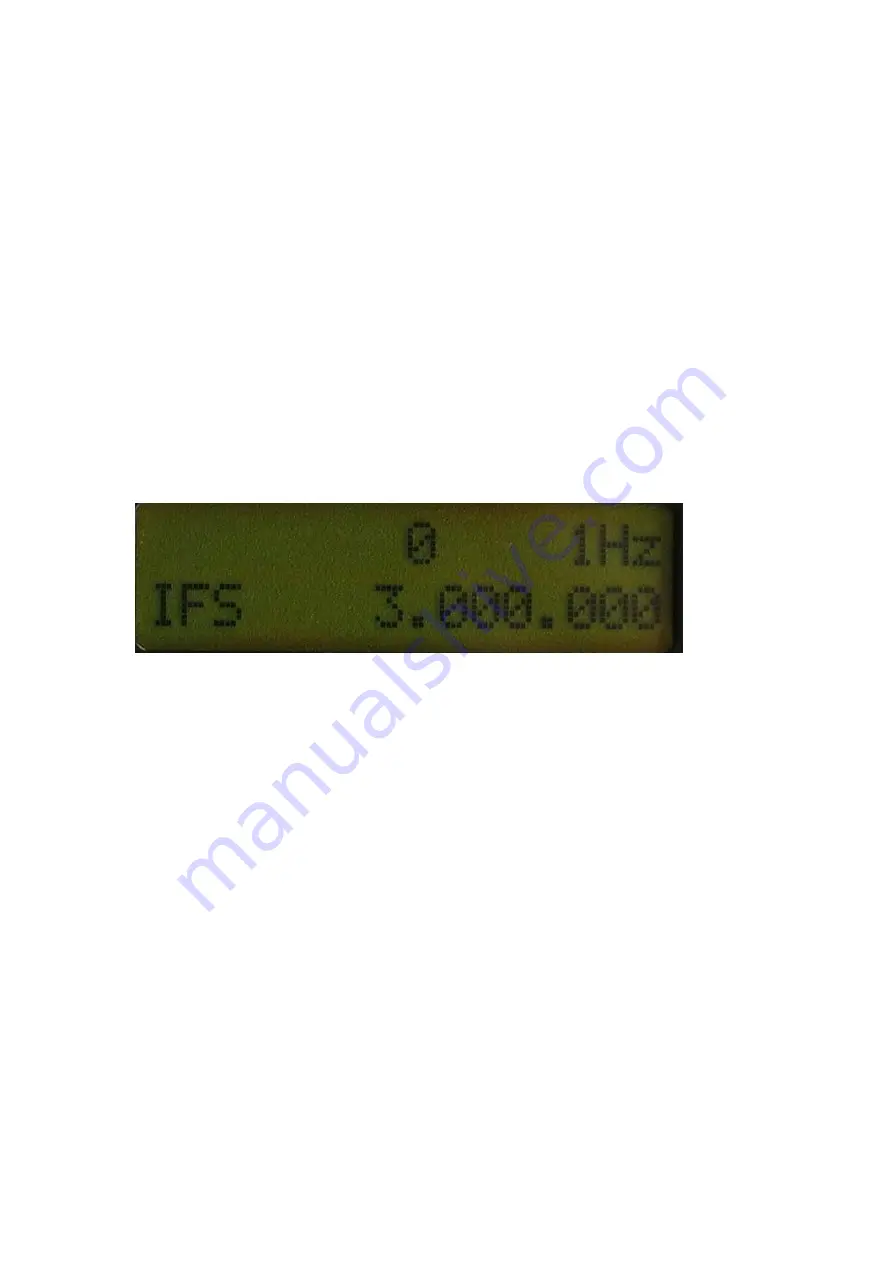
alter the value to 2800, so that LSB and USB are 1.4 kHz from the center frequency. Press
the MEM button to save the modified data. Press SETUP to exit.
Monitor the frequency meter. Tune from 3 - 18.199999 MHz using LSB mode, the reading
is always 9 MHz higher than the DDS LCD displays. If the frequency is not very accurate
at higher band frequencies, re-calibrate the clock. Press MOD to enter USB mode, the
measured frequency is 2.4kHz higher. Now, let's calibrate the IF.
Press the SETUP button, IFS information appears on the screen. "0" indicates the default
IF value which is 9 MHz. In this kit, the BFO frequency at LSB mode is 8.998400 MHz, not
9.00000 MHz.
(900000
–
8998400) = 1600, i.e., 1.6 kHz. The DDS should be 1.6kHz lower to match the
LCD display. Please turn the TUNE control counter-clockwise until -1600 appears on the
LCD screen. Press MEM to save this modified data. Press SETUP or other function keys
to exit SETUP.
Now let's move up to the main board.
2. Main Board
Note
–
there are no components at C21
A few bulkier components should be assembled:
1) Two DC input sockets
2) Power switch
3) PTT switch (Do not put on the push button until the whole kit is completed.)
4) Phone socket (3.5mm stereo socket.
Do not
cut the stand-off and file the rim like J1 of
DDS board.)
5) Connectors: CN3, CN4, CN5, CN6, CN7 (Note: CN7 is assembled on the back to
shorten the leads from the battery pack.)
Содержание TJ2B
Страница 3: ...Cables for internal connections Components package...
Страница 4: ...Toroids Note FB 43 2401 may be supplied in the kit This core is larger than FT 43 37 Can Inductors...
Страница 5: ...Pre assembled Miniature Transformers Packed in a separate plastic bag Brass Stand Off Parts...
Страница 10: ...How to insert the LCD Cable Never bend the cable end soldered to the LCD...
Страница 12: ...Now solder the 7 wire cable...
Страница 24: ...T7 is soldered on the 3 lead pads with the tap in then middle pad No connection on the 2 pin lpads...
Страница 35: ...50 ohm cable and MIC cable are connected How the cable is soldered...
Страница 37: ...See how to arrange the 5 wire ribbon cable...
Страница 40: ...Don t forget to solder ANT leads Assemble the two brass stands off with a tai to the mounting holes...


