Imagined by You
™
www.tiohome.com
AZSS1 Installation Guide
9
STEP 6
Skip to Step 7 if you are using the Cat5 power wiring via
the TiO Remote Power Coupler (AZPC1).
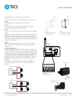
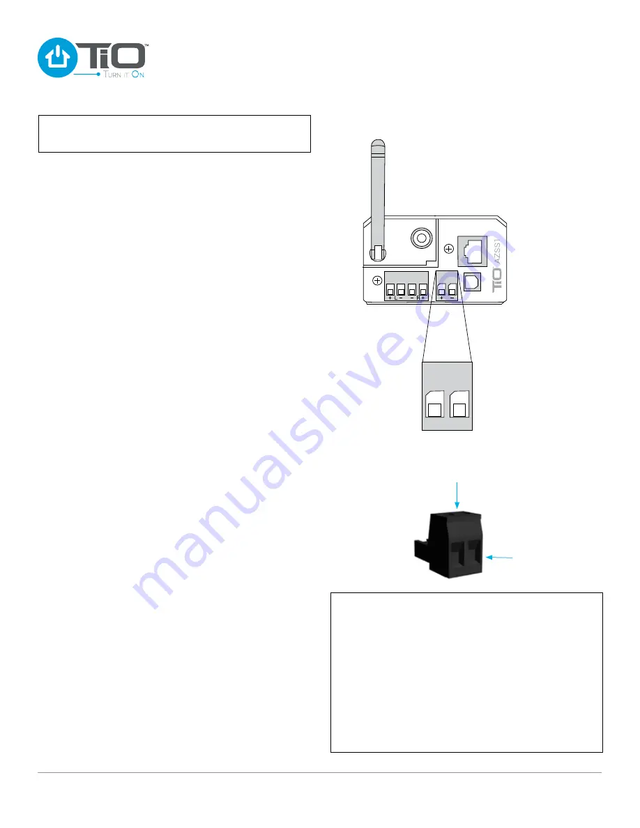
Locate the AZPS1 power supply. To connect the power supply
to the AZSS1 you will need to locate the Power Connector for
the AZSS1. The power connector is located in a clear pack of
accessories in the AZSS1 package. With the Power Connector
in your hand, loosen the two screws, so that the two power
wires can be inserted, then tighten down each screw. Note the
polarity: Left positive (+), Right negative (–). Plug the Power
Connector into the the back of the AZSS1.
Note: Make sure locking tabs on mating side of the Power
Connector locks over the top of the receiving connector on
the AZSS1. Skip to Step 8.
STEP 7
Locate the AZPS1 power supply. To connect the power supply
to the AZPC1 you will need to locate the Power Connector for
the AZSS1. The power connector is located in a clear pack of
accessories in the AZSS1 package. With the Power Connector
in your hand, loosen the two screws, so that the two power
wires can be inserted, then tighten down each screw. Note
the polarity: Left positive (+), Right negative (–). Insert Power
Connector into power socket on the AZPC1.
STEP 8
Network connection. If you are using an Ethernet Cable for
network, plug it in now. No action required, at this time, if
connecting using Wi-Fi.
STEP 9
Attach the optical Line-In if adding a digital input source, and
Line-Out if connecting to a external amplifier.
STEP 10
With all connections securely connected to the back of the
AZSS1, insert the AZSS1 into the low voltage single gang ring
and secure it using the two included screws in the package.
STEP 11
For Stand-alone use, connect the Ethernet cable from the
AZSS1 to the home network router (for Wi-Fi connection see
Connecting Using WPS).
For Multi-space use, connect the Ethernet cable from the
AZSS1 to the Master Coordinator (MC1).
STEP 12
With the AZSS1 securely mounted, plug the AZPS1 into an
outlet. The AZSS1 takes approximately one minute to complete
its power up cycle. The AZSS1 Installation is complete.
WARNING: This product should not be mounted in any
box that also has electrical products such as light switches
or outlets installed. Electrical interference from a light
switch or outlet can create unwanted background noise
on your audio space.
IMPORTANT: It is not recommended to mount multiple
AZSS1’s next to each other when connecting over Wi-Fi.
Installing multiple wireless AZSS1’s near each other could
effect their ability to connect wirelessly to the MC1.
DANGER: Avoid all electrical wiring when cutting the rough
opening. Failure to do so may result in serious injury
or death.
NOTE: The power supply used by the AZSS1 is a 90W power
supply rated at 3.75amps (sold separately).
STEP 6
Removable
Power Connector
+ –
+ –
Insert Power
Wires
Loosen Screws


