


Hardware Operation Manual
27
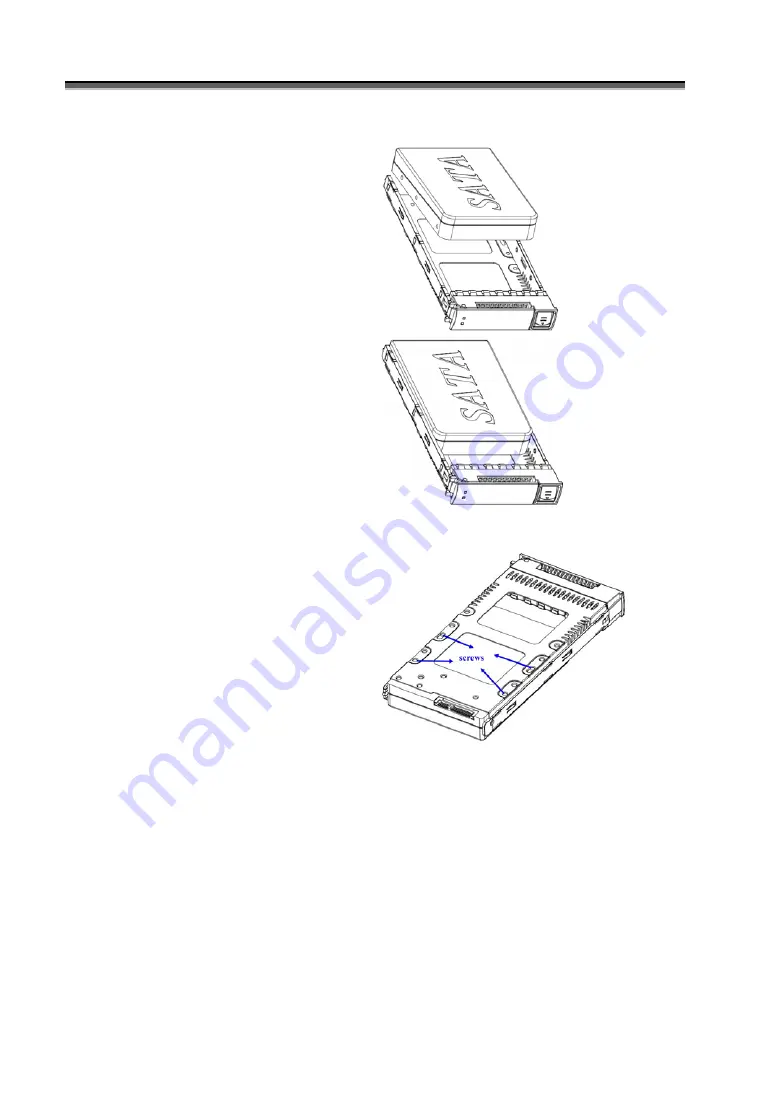
Install HDDs.
1) Put HDD into the Cartridge.
2) Align 4 screws holes on both HDD &
Cartridge.
3) Fasten all 4 screws to mount HDD in
the cartridge and make sure the HDD
is properly tightened.
Install Cartridges
Reversed the procedures of “Remove
cartridges” to install cartridges back
to JBOD system.
Содержание 3 SAS
Страница 1: ...Yotta 3 SAS SATA JBOD Enclosure User Guide Ver 1 0...
Страница 13: ...Hardware Operation Manual 13 Y3 16S6JS6 Y3 12S6JS6...
Страница 15: ...Hardware Operation Manual 15 Y3 12S6JS6 D...
Страница 43: ...Hardware Operation Manual 43 One SAS Raid subsystem with one SAS JBOD Tower...
Страница 44: ...Hardware Operation Manual 44 One SAS Raid subsystem with two SAS JBOD Tower IN OUT OUT...
Страница 45: ...Hardware Operation Manual 45 One SAS Raid subsystem with three SAS JBOD Tower IN OUT OUT...
Страница 46: ...Hardware Operation Manual 46 One SAS Raid subsystem with four SAS JBOD Tower IN OUT OUT...


