manualshive.com logo in svg
background image


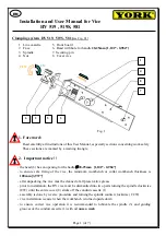
3. Standard Clamping by Turning the Spindle 

By turning the spindle (3) clockwise (CW) the vice clamp. By turning the spindle (3) counter 

clockwise (CCW) the vice disengage. 


4. General Instructions 

The wood vice is mounted to the lateral face of a workbench flush with the outside edge. The 

exact position is selected depending on the design of the workbench and HV vice size. Is 
recommended vice installation on 

workbench with collar

.  The most common HV vice installation is 

illustrated in Fig. 2a, 2b, 2c.  


Cover vice installation on workbench 


Page 2 (of 7) 

Spacer underneath

 the cover


min A 

mm ["] 

min B 

mm ["] 

mm ["] 

HV 519 a 519S 

[0,197“] 

395 [15,551“] 

88 [3,465“] 

HV 581 

[0,197“] 

348 [13,701“] 

88 [3,465“] 

Fig. 2a 

Workbench 
collar  

Workbench board, min. 
thickness 100mm [3,937“]  

Spacer 

underneath the 

cover vice 

Clamping jaw with 

of the conduit 

cassette 

Cover vice 

Содержание HV 519S

Страница 1: ...0 984 to ensure safe fixing of the vice the minimum workbench or collar workbench thickness is 100mm 3 937 after unpacking the vice must be cleaned of all preservative grease prior to installation the...

Страница 2: ...nding on the design of the workbench and HV vice size Is recommended vice installation on workbench with collar The most common HV vice installation is illustrated in Fig 2a 2b 2c Cover vice installat...

Страница 3: ...h board thickness corresponding jaw thickness Depth of mortising on front board 5 min 9 0 354 gross up of size bolthead Line cassette Spacer underneath the cover vice Cover vice Fig 2b Fig 2c Guiding...

Страница 4: ...with spacer axially symmetrical so that spacer is not interfered a guiding grooves of the conduit cassette Cover vice use after screw as template drilling hole 14 for securing pins only HV519 and HV51...

Страница 5: ...0 for HV 519 S and HV 581 See Fig 4a Then is must insert eventually glue together to remainder parts Finally is screw the line cassette See Fig 4b 7 Completion mounting clamping jaw The spindle comple...

Страница 6: ...collar nut is secure sole piece and screw M8 from the inside the workbench If the workbench has no collar spindle of the conduit cassette secure her position b Prior to bolting spindle and nut the fac...

Страница 7: ...ch board See Fig 7 f Finally check the operation of the vice s system By turning the spindle 3 clockwise CW the vice clamp By turning the spindle 3 counter clockwise CCW the vice disengage Vice disass...

Отзывы: