


Manifold gas pressure may be measured by two different
procedures. It may be measured with the burner box cover in
place or it may be measured with the burner box cover re-
moved. Follow the appropriate section, 2a or 2b in the instruc-
tions below.
1. Turn gas off at main gas valve. Remove 1/8" Allen socket head
pipe plug from the manifold end of the main gas valve. Install
the proper manometer tube adapter into this opening.
2. Read the inlet gas pressure using either of the two methods
below.
a. Reading the gas pressure with the burner box cover in
place - Disconnect the pressure reference hose from
the right side of the burner box. Using a tee fitting and
a short piece of hose, connect the negative side of the
manometer to the burner box pressure reference port
as shown in Figure 33 or 34. Connect the positive side
of the manometer to the adapter previously installed in
the gas valve as shown in Figure 33 or 34.
b. Reading the gas pressure with the burner box cover
removed - Remove the screws securing the burner box
front cover plate. Remove the cover. It is gasketed and
may stick in place. Connect the positive side of the
manometer to the adapter previously installed in the
gas valve as shown in Figure 33 or 34. There will be no
second connection to the manometer as it will refer-
ence atmospheric pressure.
NOTE: The screw-off cap for the pressure regulator must be removed
entirely to gain access to the adjustment screw. Loosening or
tightening the cap does not adjust the flow of gas.
3. Refer to Figure 32 for location of pressure regulator adjust-
ment cap and screw on main gas valve.
4. Turn gas and electrical supplies ON. Start furnace and
observe manifold pressure on manometer.
5. Adjust manifold pressure by adjusting gas valve regulator
screw: for natural gas, set at 3.5" W.C.
If gas valve regulator is turned in, or clockwise, manifold
pressure is increased. If screw is turned out, or counterclock-
wise, manifold pressure will decrease.
WARNING: If manifold pressure is too high, an over-
fire condition exists which could cause heat ex-
changer failure. If the manifold pressure is too low,
sooting and eventual clogging of the heat exchanger
could occur.
Natural Gas 3.5" W.C.
6
5
4
3
2
1
0
1
2
3
4
5
6
G A S
V A L V E
U - T U B E
M A N O M E T E R
B U R N E R B O X
W I T H C O V E R
3 . 5 I N .
W A T E R C O L U M N
G A S P R E S S U R E
S H O W N
B U R N E R B O X
P R E S S U R E
R E F E R E N C E H O S E
O U T L E T
P R E S S U R E
T A P
T E E F I T T I N G
6
5
4
3
2
1
0
1
2
3
4
5
6
G A S
V A L V E
U - T U B E
M A N O M E T E R
B U R N E R B O X
W I T H C O V E R R E M O V E D
3 . 5 I N .
W A T E R C O L U M N
G A S P R E S S U R E
S H O W N
B U R N E R B O X
P R E S S U R E
R E F E R E N C E H O S E
( N O T U S E D )
O U T L E T
P R E S S U R E
T A P
GAS
VALVE
U-TUBE
MANOMETER
BURNER BOX
WITH COVER
3.5 IN.
WATER COLUMN
GAS PRESSURE
SHOWN
BURNER BOX
PRESSURE
REFERENCE HOSE
OUTLET
PRESSURE
TAP
6
5
4
3
2
1
0
1
2
3
4
5
6
TEE
FITTING
6
5
4
3
2
1
0
1
2
3
4
5
6
GAS
VALVE
U-TUBE
MANOMETER
BURNER BOX
WITH COVER REMOVED
3.5 IN.
WATER COLUMN
GAS PRESSURE
SHOWN
BURNER BOX
PRESSURE
REFERENCE HOSE
(NOT USED)
OUTLET
PRESSURE
TAP
FIGURE 33 - UPFLOW
MODELS
-
READING
GAS
PRESSURE:
WITH
BURNER
BOX
COVER
IN
PLACE WITH
BURNER
BOX
COVER
REMOVED
FIGURE 34 - DOWNFLOW/HORIZONTAL FLOW MODELS - READING GAS PRESSURE:
WITH
BURNER
BOX
COVER
IN
PLACE WITH
BURNER
BOX
COVER
REMOVED
650.75-N4U
22
Unitary Products Group
Содержание 65075-N4U
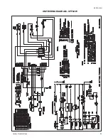
Страница 29: ...UNIT WIRING DIAGRAM UPFLOW 650 75 N4U Unitary Products Group 29...
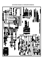
Страница 30: ...UNIT WIRING DIAGRAM DOWNFLOW HORIZONTAL...
Страница 31: ...NOTES 650 75 N4U Unitary Products Group 31...


