


WARNING: Blower and burner must never be oper-
ated without the blower panel in place.
Electrical supply to this unit is dependent upon the panel that
covers the blower compartment being in place and properly
positioned.
CAUTION: Main power to the unit must still be inter-
rupted at the main power disconnect switch before
any service or repair work is to be done to the unit. Do
not rely upon the interlock switch as a main power
disconnect.
Rollout Switch Controls
This control is mounted on the burner box assembly. If the
temperature in the burner compartment exceeds its set point,
the igniter control and the gas valve are deenergized. The
operation of this control indicates a malfunction in the combus-
tion air blower, heat exchanger or a blocked vent pipe connec-
tion. Corrective action is required. This is a manual reset control
and must be reset before operation can continue.
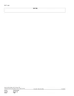
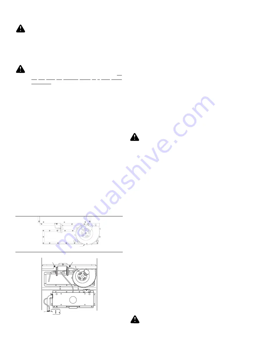
Pressure Switches
This furnace is supplied with pressure switches which monitor
the flow through the combustion air/vent piping system. These
switches de-energize the ignition control module and the gas
valve if any of the following conditions are present. Refer to
Figure 31 for tubing connections
1. Blockage of combustion air piping or terminal. (1LP)
2. Blockage of vent piping or terminal (1LP).
3. Failure of combustion air blower motor (1LP).
4. Blockage of condensate drain piping:
- Upflow units (1LP)
- Downflow/Horizontal Units
- Downflow (1LP)
- Horizontal Left (1LP)
- Horizontal Right (2LP)
Limit Control
There are high temperature limit control(s) located on the
furnace vestibule panel near the gas valve. These are automat-
ic reset control and provides over temperature protection due
to reduced airflow, such as a dirty filter.
Auxiliary Limit Controls
Downflow/horizontal units have a single limit switch mounted
on the blower assembly. This is a manual reset control and gives
high temperature protection in the event of a blower motor
failure.
START-UP AND ADJUSTMENTS
The initial start-up of the furnace requires the following addi-
tional procedures:
1. When the gas supply is initially connected to the furnace,
the gas piping may be full of air. In order to purge this air,
it is recommended that the ground union be loosened until
the odor of gas is detected. When gas is detected, imme-
diately retighten the union and check for leaks. Allow five
minutes for any gas to dissipate before continuing with the
start-up procedure.
WARNING: Be sure proper ventilation is available to
dilute and carry away any vented gas.
2. The condensate trap must be filled with water before
putting the furnace into operation. The recommended pro-
cedure is as follows:
a Disconnect the condensate drain hose from the induced
draft blower discharge.
b. Elevate this hose and fill with water using a funnel.
c. Replace the condensate drain hose and clamps.
3. All electrical connections made in the field and in the
factory should be checked for proper tightness.
IGNITION SYSTEM SEQUENCE
1. Turn the gas supply ON at external valve and main gas
valve.
2. Set the thermostat above room temperature to call for heat.
3. System start-up will occur as follows:
a. The induced draft blower motor will start and come up
to speed. Shortly after venter start-up, the hot surface
igniter will glow for about 17 seconds.
b. The ignition module will energize (open) the main gas
valve for seven seconds.
c. After flame is established, the supply air blower will
start in about 30 seconds.
NOTE: Burner ignition may not be satisfactory on first start-up
due to residual air in line.
4. With furnace in operation, paint the pipe joints and valve
gasket lines with a rich soap and water solution. Bubbles
indicate a gas leak. Take appropriate steps to stop the leak.
If the leak persists, replace the component.
WARNING: DO NOT omit this test! Never use a flame
to check for gas leaks.
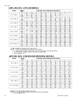
CHECKING GAS INPUT (NATURAL GAS)
1 L P
2 L P
DOWNFLOW
HORIZONTAL
2LP
1LP
FIGURE 31 -PRESSURE SWITCH TUBING ROUTING
BURNER BOX
1LP
INDUCTED DRAFT
BLOWER
UPFLOW
650.75-N4U
20
Unitary Products Group
Содержание 65075-N4U
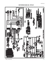
Страница 29: ...UNIT WIRING DIAGRAM UPFLOW 650 75 N4U Unitary Products Group 29...
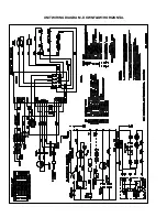
Страница 30: ...UNIT WIRING DIAGRAM DOWNFLOW HORIZONTAL...
Страница 31: ...NOTES 650 75 N4U Unitary Products Group 31...


