107273-UUM-C-0306
18
Unitary Products Group
Your Service Technician
Your furnace's best friend is your qualified service technician. If the unit
gives any indication of improper operation, call your service technician.
If the service technician is allowed to perform the normal routine care of
your furnace, he can many times detect potential difficulties and make
corrections before trouble develops. Preventative maintenance of this
type will allow you to operate the unit with a minimum of concern, and at
the same time will pay for itself in added years of comfort.
When You Call For Service Assistance
Very often time can be saved if you will give the service agency the
MODEL and SERIAL NUMBER of your furnace. This will enable him to
determine the specific components used, and perhaps to better identify
the possible problem and be better prepared if a service call is required.
To Contact Your Serviceman
(fill in)
COMPANY:___________________________________________
ADDRESS: __________________________________________
TELPHONE:__________________________________________
If Furnace Fails to Operate Properly
1.
Check setting of thermostat - and position of HEAT/COOL switch if
air conditioning is installed. If a set-back type thermostat is
employed be sure that the thermostat is in the correct operating
mode.
2.
Check to see that electrical power is ON.
3.
Check to see that the knob or switch on the gas control valve is in
the full ON position.
4.
Make sure filters are clean, return grilles are not obstructed, and
supply registers are open.
5.
Be sure that furnace flue piping is open and unobstructed.
If the cause for the failure to operate is not obvious, do not attempt to
service the furnace yourself. Call a qualified service agency or your gas
supplier.
START-UP AND SHUTDOWN INSTRUCTIONS
Read the Instructions Below Before Trying to Start the
Furnace
A.
This appliance does not have a pilot. It is equipped with an
ignition device which automatically lights the burner. Do not
try to light the burner by hand.
B.
BEFORE OPERATING; smell all around the appliance area
for gas. Be sure to smell next to the floor because some gas
is heavier than air and will settle on the floor.
C.
Use only your hand to push the gas control switch to the “on”
position. Never use tools. If the switch will not operate by
hand, don’t try to repair it, call a qualified service technician.
Force or attempted repair may result in a fire or explosion.
D.
Do not use this appliance if any part has been under water.
Immediately call a qualified service technician to inspect the
appliance and to replace any part of the control system and
any gas control, which has been under water.
Operating Instructions:
1.
STOP! Read the safety information above.
2.
Set the thermostat to the lowest setting.
3.
Turn off all electric power to the appliance.
4.
Remove furnace door.
5.
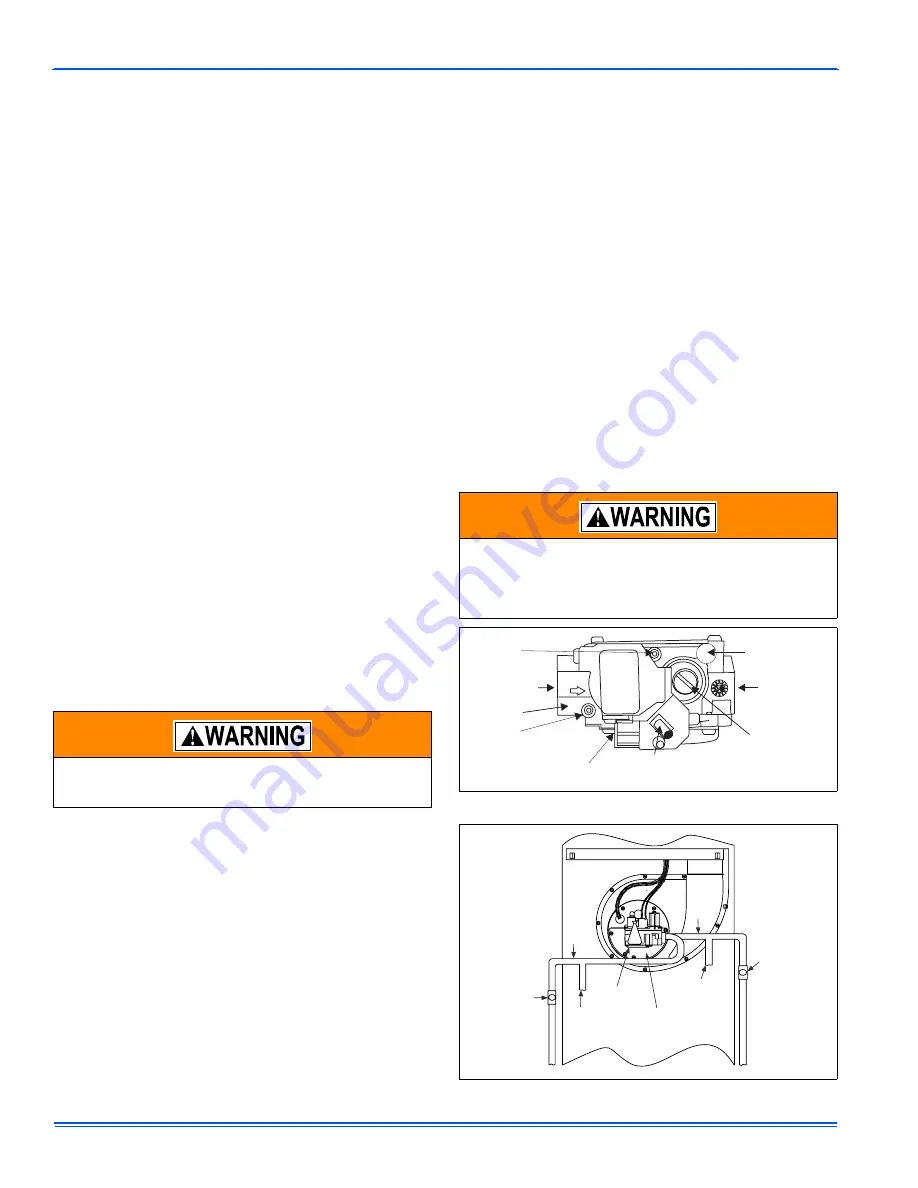
Move gas control switch to the “OFF” position. Do not force. See
Figure 18.
6.
Wait five (5) minutes to clear out any gas. If you then smell gas,
STOP! Follow “B” in the safety information above. If you don’t
smell gas, go to next step.
7.
Move gas control switch to the “ON” position. Do not force. See
Figure 18.
8.
Replace burner door.
9.
Turn on all electric power to the appliance.
10. Set thermostat to the desired setting. Burner will light, which may
take 30-60 seconds.
11.
After three (3) trials for ignition, if the appliance will not operate fol-
low the instructions, “TO TURN OFF THE APPLIANCE” and call
your service technician or gas supplier.
To Turn Off the Appliance:
1.
Set the thermostat to lowest setting.
2.
Turn off all electric power to the appliance if service is to be per-
formed.
3.
Remove burner access panel.
4.
Move gas control switch to the “OFF” position. See Figure 18.
5.
Replace burner access panel.
If you do not follow these instructions exactly, a fire or
explosion may result causing property damage, personal
injury, and/or loss of life.
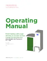
Should overheating occur, or the gas valve fail to shut off,
turn the external manual gas valve in the gas supply line to
the furnace to the “off” position and let the furnace cool off
before shutting off the electrical power supply. Refer to
Figure 19.
FIGURE 18: Gas Valve
FIGURE 19: Gas Piping
Inlet
Wrench
Boss
Inlet
Pressure Port
ON
OFF
On/Off Switch
(Shown in ON position)
Main Regulator
Adjustment
Outlet
Outlet
Pressure Port
Vent Port
1/4” Quick Connect
Electrical Terminals
MANUAL
SHUT-OFF
VALVE
GAS
PIPE
GAS
PIPE
MANUAL
SHUT-OFF
VALVE
GAS
VALVE
GAS
BURNER
DRIP
LEG
DRIP
LEG
Содержание DFAA
Страница 15: ...107273 UUM C 0306 Unitary Products Group 15 FIGURE 14 Wiring Diagram for DFAH Oil Fired Furnace ...
Страница 22: ...107273 UUM C 0306 22 Unitary Products Group FIGURE 21 Wiring Diagram for DFAH Gas Conversion Burner ...
Страница 31: ...107273 UUM C 0306 Unitary Products Group 31 NOTES ...


