


<Toc>
<6. Parameters>
6-7
IM 05E01D02-41E
●
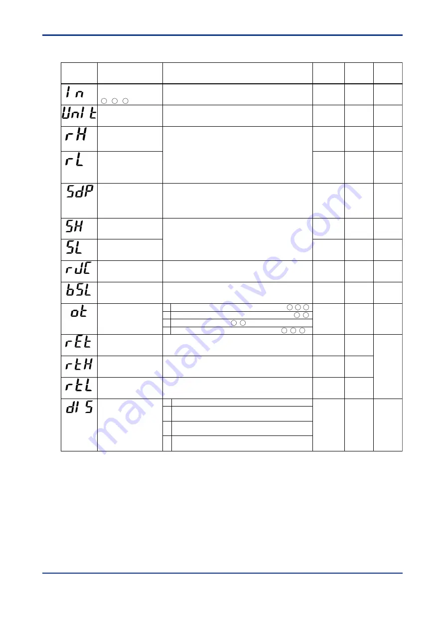
Input-/Output-related Parameters
Parameter
Symbol
Name of Parameter
Setting Range and Description
Initial Value
PV input type (PV INPUT
terminals)
- - terminals
OFF (0)
PV input unit
°
C (0): Degree Celsius
°
F (5): Fahrenheit
(This parameter is not shown for voltage input.)
°
C (0)
Max. value of PV input
range
Min. value of PV input
range
Max. value of
instrument
input range
Min. value of
instrument
input range
Instrument input range, however RL < RH
-Temperature input
Set the range of temperature that is actually controlled.
- Voltage input
Set the range of a voltage signal that is applied. The scale across which the
voltage signal is actually controlled should be set using the parameters
Maximum Value of PV Input Scale (SH) and Minimum Value of PV Input
Scale (SL).
PV input decimal point
position (displayed
at voltage input)
Max. value of PV input
scale
(displayed at voltage input)
Min. value of PV input
scale
(displayed at voltage input)
0 to 3
Set the position of the decimal point of voltage-mode PV input.
0: No decimal place
1: One decimal place
2, 3: Two, three decimal places
1
100.0
-1999 to 9999, however SL < SH
Set the read-out scale of voltage-mode PV input.
0.0
User Setting
Target Item
in CD-ROM
(IN)
(UNIT)
(RH)
(RL)
(SDP)
(RJC)
(SH)
(SL)
Selection of PV input
burnout action
OFF (0)
1: Up scale
2: Down scale
1
Presence/absence of
PV input reference
junction compensation
OFF (0), ON (1)
ON (1)
(BSL)
Control output type
0
(OT)
DI function selection
OFF (0)
(DIS)
Retransmission output
type
OFF (0): Does not work.
1: PV, 2: SP, 3: OUT, 4: Loop power supply for sensor (15 V)
1
Max. value of
retransmission output
scale
Min. value of
retransmission output
scale
RET=1, 2: RTL + 1 digit to 100% of PV input range
RET=3: RTL + 1 digit to 100%
RET=1, 2: 0% of PV input range to RTH - 1 digit
RET=3: 0% to RTH - 1 digit
100% of
PV input
range
0% of
PV input
range
(RET)
(RTH)
(RTL)
OFF (0), 1 to 18, 30, 31, 35 to 37, 40, 41, 50, 51, 55, 56
See Instrument Input Range Codes in “2. Initial Settings.”
13
12
11
0
1
2
3
Time proportional PID relay contact output (terminals - - )
1
2
3
Time proportional PID voltage pulse output (terminals - )
16 17
Current output (terminals - )
16 17
ON/OFF control relay contact output (terminals - - )
1
2
3
Disables the external contact input.
DI1: Starts (on)/stops (off) program-1 operation.
DI2: Starts (on)/stops (off) program-2 operation.
DI1: Hides (on)/shows (off)) the LOCK setup parameter.
DI2: Unused.
DI1: Starts (on)/stops (off) program-1 operation.
DI2: Enables (on)/disables (off) the hold mode of program-1 operation.
OFF
1
2
3
ᎏ
ᎏ
ᎏ
ᎏ
ᎏ
ᎏ
ᎏ
ᎏ
ᎏ
ᎏ
Ref.2.2(1)
Ref.3.1(5)
1st Edition : May 31,2000-00
Содержание UP350
Страница 2: ...Blank Page ...
Страница 52: ...Blank Page ...
Страница 62: ...Blank Page ...
Страница 72: ...Blank Page ...
Страница 94: ...Blank Page ...
Страница 96: ...Blank Page ...