background image

IM 5E1E70-01E

27

(4)

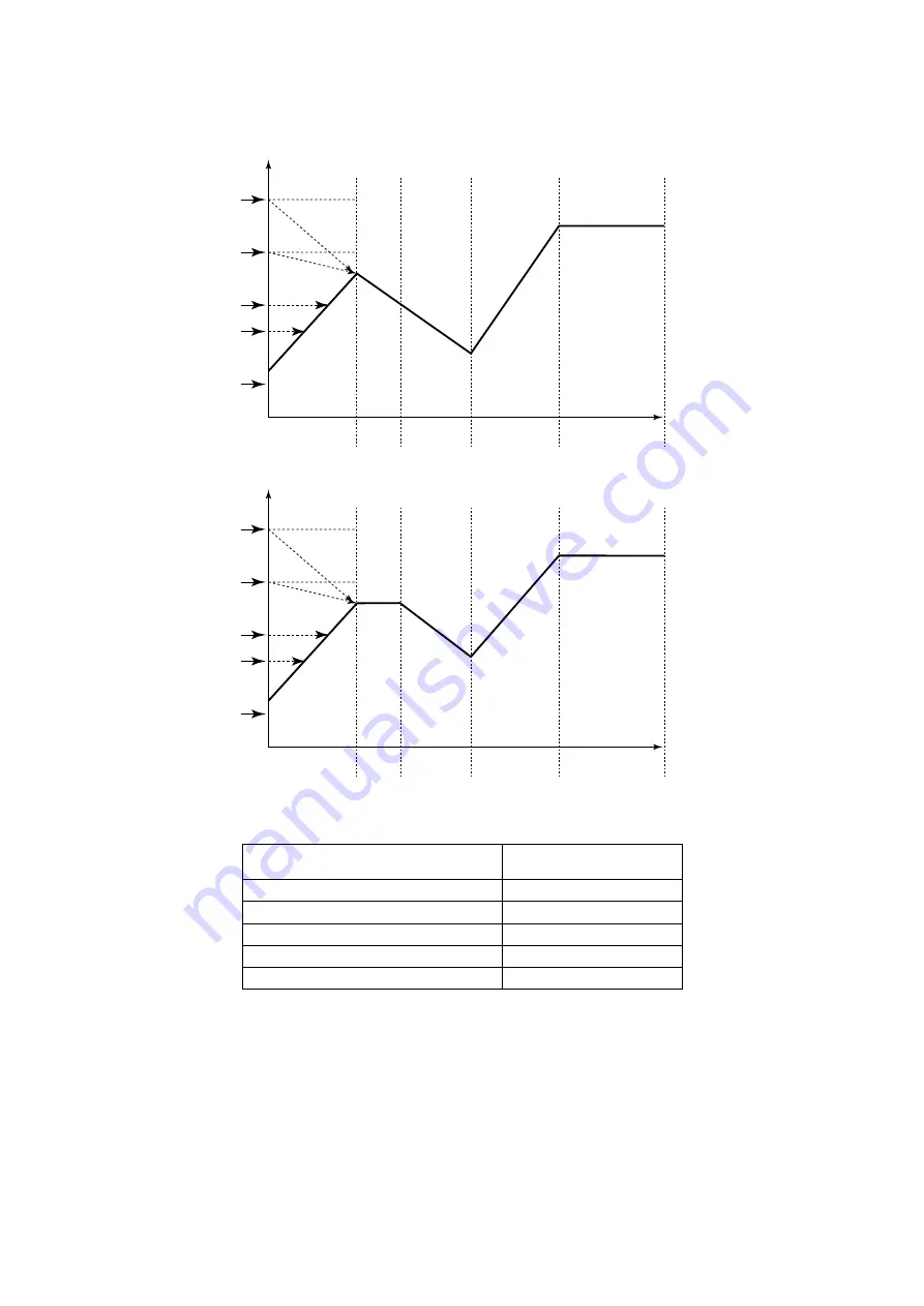
In the case of other program pattern is set.
The starting point of program-driven operation is any of points A (SSP) to D.

PV

1

2

3

4

5

C

D

B

A(SSP)

Seg.1

Seg.2

Seg.4

Seg.5

Seg.3

Time

PV

1

2

3

4

5

C

D

B

A(SSP)

Seg.1

Seg.2

Seg.4

Seg.5

Seg.3

Time

The starting point of program-driven operation is determined by where the measured input value (PV) is
located at the time the operation starts.

Starting point of program-

driven operation

Measured input value (PV) at startup of

program-driven operation

D

D

C

B

A (SSP)

1

2

3

4

5

Содержание UP150

Страница 1: ...Instruction Manual UP150 Program Controller IM 5E1E70 01E IM 5E1E70 01E 1st Edition ...

Страница 2: ...controller and keep it handy for quick reference CONTENTS 1 Notice 3 2 What is on the Front Panel 4 3 Installing the Controller 5 4 Panel Cutout Dimensions and External Dimensions 6 5 Wiring 7 6 Hardware Specifications 9 7 Key Operations 10 8 Program Operating Function 21 9 Troubleshooting 32 ...

Страница 3: ... controller Mounting bracket Instruction manual IM 5E1E70 01E 1 1 1 Model Model and Suffix Codes Suffix code Description UP150 Program controller V A Voltage pulse output time proportional PID 4 to 20mA output continuous PID Digital input to switch Mode HOLD RUN Communication function MODBUS Personal computer link Option EX RS Control output for general purpose temperature control ...

Страница 4: ...of personnel and or damage to the product In the manual the symbol is accompanied by an explanation of the special care that is required to avoid shock or other dangers that may result in injury or loss of life The following symbols are used in this manual only IMPORTANT Indicates that operating the hardware or software in a particular manner may lead to damage or result in system failure NOTE Dra...

Страница 5: ...g down the key will gradually increase the speed of changes Pressing this key in operation display stop resets the program operation h Data change key Run key Changes the parameter values Pressing this key decreases the data value Holding down the key will gradually increase the speed of changes Pressing this key in operation display starts run the program operation i SET ENT key data resistering ...

Страница 6: ...e maintained at about 23 C 8 There is no splashing of water and with minimal fluctuation 9 There are no flammable materials 5 There is no direct heat radiation Never place the controller directly on flammable items If the controller has to be installed close to flammable items or equipment be sure to enclose the controller in shielding panels positioned at least 150mm away from each side These pan...

Страница 7: ...ckness max 47 8 max 44 8 max 44 8 100 12 1 to 10 Unit mm 1 General Mounting min 70 min 70 45 0 6 0 45 0 6 0 25 25 N 1 48 45 0 6 0 0 8 0 45 2 Side by side Close Mounting Splash proof construction is unavailable N is the number of controllers If N 5 then measure the actual length 48 48 ...

Страница 8: ...andards and clearly indicate that the device is used to de energize the controller 2 For thermocouple input use shielded compensating lead wires For RTD input use shielded wires which have low resistance and no resistance difference between the 3 wires See the table given later for the specifications of the cables and terminals and the recommended products NOTE Always fix a terminal cover bracket ...

Страница 9: ...UN HOLD COM RS 485 3 4 5 EV2 EV1 COM RSB RSA SG 4 to 20 mA Output Voltage Pulse Output Control Output Power Supply 9 L N 10 Event Outputs Specify one for the output signal type Universal input selectable input type When RS is specified When EX is specified 11 12 13 14 15 14 15 Note You are not allowed to specify both the RS and EX options at the same time ...

Страница 10: ...90 RH no condensation allowed Magnetic field 400AT m or less Continuous vibrations of 5 to 14Hz Amplitude of 1 2mm or less Continuous vibrations of 14 to 150Hz 4 9m s2 0 5G or less Short period vibrations 14 7m s2 1 5G for 15 seconds or less Shock 147m s2 15G for 11 milliseconds or less Mounting angle Upward incline of up to 30 degrees downward incline is not allowed Altitude 2000m or less above s...

Страница 11: ...the key for at least 3 seconds transfers back to the operation display Registering the parameter PRG to 1 retrieves the program parameter setting display 6 At the program parameter setting display pressing the key for at least 3 seconds transfers back to the operation display When In appears press the key to display the input range code you want to use then press the key to register it After this ...

Страница 12: ...r CTL determines whether the other param eters are displayed or not The flowchart P XXXXX will help you understand how this works Step 1 Confirm that the controller shows the operation display or Step 2 To enter the Operating parameter setting display press the key for at least 3 seconds When UP150 is in Program operation the HOLD appears in the display When UP150 is not in Program operation the C...

Страница 13: ... ONF on off control Displayed when the operation mode is RUN CTL PID Displayed when I 0 Displayed for time proportional PID control Displayed when EX is specified LOC PRG When 1 When 1 When 0 1 or 2 When LOC 1 transfers to the setup parameter setting display When RPG 1 transfers to the program parameter setting display Press the key to move between items Displayed for the RS option Not displayed w...

Страница 14: ...troller shows the operation display 1 Press the key for at least 3 seconds To operation display 1 Note Press the key to move between items NOTE A Program parameter setting display AL1 A1 HY1 AL2 A2 HY2 EON1 EOF1 EON2 EOF2 EV1 EV2 SSP SP1 TM1 SP2 TM2 SP3 TM3 SP4 TM4 SP5 TM5 SP6 TM6 JC WTZ SP7 TM7 SP8 TM8 SP9 TM9 SP10 TM10 SP11 TM11 SP12 TM12 SP13 TM13 SP14 TM14 SP15 TM15 SP16 TM16 ...

Страница 15: ...IM 5E1E70 01E 14 This page left intentionally blank ...

Страница 16: ...0 50 0 HYS Hysteresis for on off control 0 C F to the temperature that corresponds to 100 of the measurement range span 0 5 of measurement range CT Cycle time of control output 1 to 240 seconds 30 seconds FL Input filter OFF 1 to 120 seconds OFF BS PV bias 100 to 100 of measurement range span 0 of instrument range span LOC Key lock 0 No key lock 1 No key lock note 2 Prevents all parameter changing...

Страница 17: ...troller address 1 to 99 However the number of controllers that can be connected per host device is 31 at the maximum 1 BPS Baud rate 2 4 2400 bps 4 8 4800 bps 9 6 9600 bps 9 6 PRI Parity NON Disabled EVN Even parity ODD Odd parity EVN STP Stop bit 1 or 2 bits 1 bit DLN Data length 7 or 8 bits 8 bits when ladder MODBUS RTU 7 bits when MODBUS ASCII 8 bits PRG Program parameter setting 0 Return to In...

Страница 18: ... F Min value of measurement range PV alarm HY2 PV event 2 hysterisis 0 to 100 of measurement range span Unit C F 0 5 of measurement range span EON2 Time event 2 on time OFF or 0 00 to 99 59 Hour Min OFF EOF2 Time event 2 off time OFF note or 0 00 to 99 59 Hour Min Note Time event 2 does not stop when OFF is set OFF SSP Start target setpoint 0 to 100 of measurement range span Unit C F Min value of ...

Страница 19: ...sured value Temperature setpoint Deviation setting Cls on Hysteresis Opn off Measured value Temperature setpoint Deviation setting Hysteresis Opn on Cls off Alarm setting Measured value Hysteresis Cls off Opn on Alarm setting Measured value Measured value Temperature setpoint Hysteresis Deviation setting Opn on Cls off PV event alarm type PV event alarm type PV event type code Closed contact durin...

Страница 20: ... TM5 ON time OFF time SEG1 SEG2 SEG3 SEG4 SEG5 SP1 SP2 SP3 SP4 SP5 Time event 1 ON time OFF time Time event 2 NOTE 1 When you don t want event OFF at the end of program operation Set OFF to time event 1 2 off time EOF1 or EOF2 2 When you want event ON at the start of program operation Set 0 00 to time event 1 2 on time EON1 or EON2 3 When the time of events on off time exceeds the setting time of ...

Страница 21: ...ten the life of the alarm To prevent this you can set a hysteresis band to prevent excessive on off actions for both alarm 1 and alarm 2 Digital input selection DIS When DIS ON Mode can be switched by only digital input signal In order to switch the Mode by key operation OFF must be set at DIS Note UP150 can be switched into RESET mode by key operation even if DIS ON SUPER function selection SC Th...

Страница 22: ...me for each segment Tow PV events and or two time event can be set for a program 0 C 50 C EOFF EON 100 C 30 Min 30 Min 20 Min 30 Min 30 Min 30 Min 35 Min 30 Min Segment No Destination target value SP Segment time TM Hour Min EON1 EOF1 AL1 A1 HY1 EON2 EOF2 AL2 A2 HY2 0 30 1 20 1 PV high limit 110 C 10 C Time event 1 EV1 1 PV event 1 EV1 0 Time event 2 EV2 1 PV event 2 EV2 0 1 2 3 4 5 6 7 8 9 10 11 ...

Страница 23: ...ram Please copy the table and use it to develop your own programs Device name Program No Program name Model name Serial No Segment No Destination target value SP Segment time TM EON1 EOF1 AL1 A1 HY1 EON2 EOF2 AL2 A2 HY2 1 2 3 4 5 6 7 8 9 10 11 12 13 14 15 16 Time event 1 PV event 1 Time event 2 PV event 2 Start target setpoint value SSP Junction code JC 100 0 ...

Страница 24: ...m parameter setting display Step 1 Confirm that the controller shows the operation display or Step 3 Set the parameter from EV1 to WTZ by using and keys Use or key to change the value of parameters Use key to register the setting When creating program is finished press the key at least 3 seconds to return to the operation display The period flashes while the value is being changed Creating Program...

Страница 25: ... points A SSP to C For other information see the following table Program pattern PV 1 2 3 4 5 C B A SSP Seg 1 Seg 2 Seg 4 Seg 5 Seg 3 Time Example Where Segment 2 is a Soak Interval Segment The starting point of program driven operation is determined by where the measured input value PV is located at the time the operation starts Starting point of program driven operation Measured input value PV a...

Страница 26: ... Segment 3 is a Soak Interval Segment PV 1 2 3 4 5 C D E B A SSP Seg 1 Seg 2 Seg 4 Seg 3 Time Example With No Soak Interval Segment The starting point of program driven operation is determined by a where the measured input value PV is located at the time the operation starts Starting point of program driven operation Measured input value PV at startup of program driven operation E D C B A SSP 1 2 ...

Страница 27: ...sists of an Ascending Gradient Ramp Only The starting point of program driven operation is determined by where the measured input value PV is located at the time the operation starts Starting point of program driven operation Measured input value PV at startup of program driven operation Program driven operation does not start up 1 D C B A SSP 1 2 3 4 5 1 Program driven operation does not start up...

Страница 28: ...eg 1 Seg 2 Seg 4 Seg 5 Seg 3 Time PV 1 2 3 4 5 C D B A SSP Seg 1 Seg 2 Seg 4 Seg 5 Seg 3 Time The starting point of program driven operation is determined by where the measured input value PV is located at the time the operation starts Starting point of program driven operation Measured input value PV at startup of program driven operation D D C B A SSP 1 2 3 4 5 ...

Страница 29: ...e a PV input is tracked Wait operation is available only at a segment junction that transfers from ramp to soak Wait Zone WTZ Wait Zone WTZ Time event SEGn 1 SEGn SEGn 1 The controller UP150 can move to the next segment SEGn 1 when the PV reaches wait zone The time is not elapced During the wait the timer for the program pattern progress stops so that time event EVn is held RUN lamp is flashed The...

Страница 30: ...gram driven operation is held time event and segment time are extended only by amount of the hold 1 Hold in soak internal segment TM1 TM2 TM3 TM4 TM5 ON time OFF time SEG1 SEG2 SEG3 SEG4 SEG5 SP1 SP2 SP3 SP4 SP5 Hold section timer stops Time event 1 2 Hold in ramp segment TM1 TM3 TM2 TM4 TM5 ON time OFF time SEG1 SEG2 SEG3 SEG4 SEG5 SP1 SP2 SP3 SP4 SP5 Hold section timer stops Time event 1 The SP ...

Страница 31: ...OFF time SEG1 SEG2 SEG3 SEG4 SEG5 SP1 SP2 SP3 SP4 SP5 Time event 1 The time when Advance is executed The remaining time of this segment SEG2 is canceled The program moves to the start point of next segment Effect on time events When the ON OFF action of time events are in time canceled section the status of time events are changed and these are kept in the next segment TM1 TM2 TM4 TM3 TM5 ON time ...

Страница 32: ...status are held PV events do not stop at this time The hold status continues until canceled by key operation or external contact Digital input When hold status is canceled the controller enters reset status 3 Repeat JC 2 At the program termination the controller repeats execution of same program pattern At this time the program driven operation always starts from SSP regardless of PV TM1 TM2 TM3 T...

Страница 33: ... the settings of all the parameters and set them at their proper values B o Input burnout Check the sensor wiring and correct it OOO PV over scale PV exceeds its effective range Check the input type and range settings and correct them Press any key to stop the flashing UUU PV under scale PV falls below its effective range Communication failure for RS option only 2 The controller needs to be repair...

Отзывы: