background image

8-3

IM 2558A-01EN

Other Features

10 

11 

12 

13 

14 

15 

16 

App 

Index 

Explanation

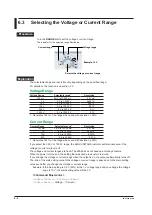
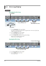
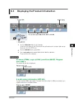
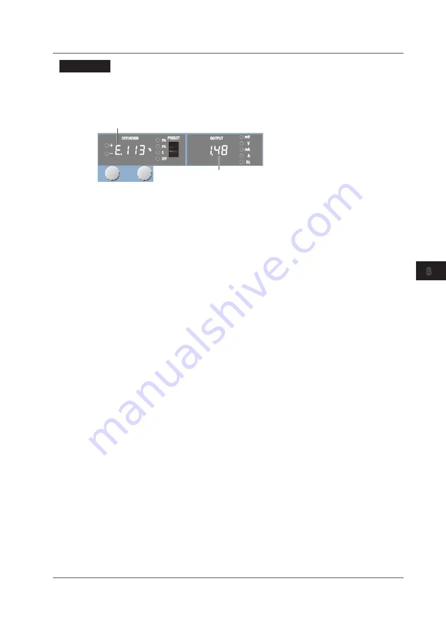
Displaying the Error Log

If there are error log entries, the deviation display shows an error code. If there are other error codes, 
turning a deviation dial shows the other error codes one by one in order.
The output display shows the total number of error log entries and which error code is being displayed.


Error code

Error log entry number

Indicates the total number of error log entries and which error log entry is being 

displayed. In this example, the first error log entry from 48 log entries is being 

displayed.

NO: 

There are no error log entries.

E.XXX:  An error code in the log. For details on error codes, see section 15.3.

8.2  Error Log Display

Содержание 2558A

Страница 1: ...IM 2558A 01EN 2nd Edition AC Voltage Current Standard 2558A...

Страница 2: ...sing YOKOGAWA products YOKOGAWA provides registered users with a variety of information and services Please allow us to serve you best by completing the product registration form accessible from our w...

Страница 3: ...rior notice as a result of continuing improvements to the instrument s performance and functionality The figures given in this manual may differ from those that actually appear on your screen Every ef...

Страница 4: ...he United States and or other countries Adobe and Acrobat are either registered trademarks or trademarks of Adobe Systems Incorporated In this manual the and TM symbols do not accompany their respecti...

Страница 5: ...usive manual may be included Please read it along with the standard manual 2 Make sure that the attached power cord meets the designated standards of the country and area that you are using it in No I...

Страница 6: ...rminal adapter Red and black 1 pc each Rating 1000 V 20 A BNC cable 366924 1 BNC BNC Length 1 m Rating 42 V 366925 1 BNC BNC Length 2 m Rating 42 V Safety terminal adapter 758923 1 set 600 V CAT II Sp...

Страница 7: ...e la structure du produit il est possible de toucher les pi ces m talliques de l adaptateur de borne fourche 758921 Proc dez avec soin car cette op ration pr sente un risque de choc lectrique ATTENTIO...

Страница 8: ...tions for proper handling or use The same symbol appears in the corresponding place in the manual to identify those instructions Electric shock danger Ground earth or functional ground terminal do not...

Страница 9: ...l or external protective earth wire or disconnect the wiring of the protective earth terminal Doing so may result in electric shock or damage to the instrument Do Not Use When the Protection Functions...

Страница 10: ...imping terminals such as the presence of foreign substances During output never touch the terminals or the connected cables when this instrument is on check that There no problems with the current ter...

Страница 11: ...xterne ni d brancher la borne de mise la terre Cela pourrait entra ner un choc lectrique ou endommager l instrument Ne pas utiliser lorsque les fonctions de protection sont d fectueuses Avant d utilis...

Страница 12: ...Il n y a aucun probl me avec les bornes d entr e de courant et les bornes de sertissage comme par exemple une pr sence de corps trangers Pendant la sortie ne pas toucher les bornes ni les c bles branc...

Страница 13: ...stic household waste Product Category With reference to the equipment types in the WEEE directive this product is classified as a Monitoring and control instruments product When disposing products in...

Страница 14: ...tions that could cause light injury to the user or cause damage to the instrument or user s data and precautions that can be taken to prevent such occurrences French AVERTISSEMENT Attire l attention s...

Страница 15: ...procedure when you are changing the settings Explanation This section describes the setup items and the limitations regarding the procedures It may not give a detailed explanation of the feature For...

Страница 16: ...dling Precautions 3 1 3 2 Installing the Instrument 3 3 3 3 Connecting to the Power Supply 3 6 3 4 Turning On and Off the Power Switch 3 8 3 5 Wiring Precautions 3 10 3 6 Connecting Cables 3 14 Chapte...

Страница 17: ...ing the Beep Sound On and Off 8 1 8 2 Error Log Display 8 2 8 3 Initializing the Settings 8 4 8 4 Displaying the Product Information 8 5 Chapter 9 USB Interface 9 1 USB Interface Features and Specific...

Страница 18: ...or Code Descriptions and Corrective Actions 15 2 15 3 Communication Error Messages 15 3 15 4 Instrument Error Detection and Clearance 15 7 15 5 Self test 15 8 15 6 Cleaning the Filter 15 9 15 7 Recomm...

Страница 19: ...1 FREQUENCY dial Switches the frequency Sections 5 2 and 6 2 OUTPUT DIVIDER section Divides the voltage or current level or the frequency output Sections 5 5 and 6 5 RANGE dial Switches the voltage o...

Страница 20: ...a PC that has a USB interface and to control the 2558A with USB TMC commands Section 9 2 External signal input terminal Used to generate voltage or current on the basis of an external oscillator frequ...

Страница 21: ...right will select the highest digit You can use this switch when the VARIABLE dial is valid FREQUENCY PHASE display Displays the set frequency set phase angle or measured frequency The following sett...

Страница 22: ...r limit of the range is reached turning the dial further will not change the number SWEEP Section The SWEEP section consists of a SWEEP switch and a pair of UP and DOWN indicators for indicating the s...

Страница 23: ...der value n m and m and n displays to show the value n dial Sets the numerator n of the divider value The range is 0 to m m dial Sets the denominator m of the divider value The range is 4 to 15 Turnin...

Страница 24: ...Because this instrument uses a 7 segment LED display numbers letters and mathematical symbols are displayed using special characters in the manner shown below Some of the characters shown below are n...

Страница 25: ...15 16 App Index 2 1 System Configuration GP IB USB USB TMC Ether VXI 11 Hi 2558A Lo I cos EXT1 EXT2 I cos EXT2 Q sin PC Command control Communication interface 2558A Slave Hi Lo DUT output target EXT...

Страница 26: ...er a high voltage caution beep will sound 1200 V 360 V 120 V 12 V Voltage 6 mA 0 1 A 0 3 A 3 A Current 100 mV 0 mV to 120 00 mV 1 V 0 V to 1 2000 V 0 5 A or higher 10 V 0 V to 12 000V approx 3 A 100V...

Страница 27: ...ing is shown on the front panel The accuracy is the same if you set one of the fixed frequencies with this feature Selectable range 40 Hz to 1000 Hz External Oscillator EXT1 To output voltage or curre...

Страница 28: ...0 A n 0 m 4 Ammeter 5 A n 2 m 4 Ammeter 10 A n 4 m 4 Frequency Output Divider If the frequency is set to FREQUENCY METER MIN or FREQUENCY METER MAX the oscillation frequency is divided and output The...

Страница 29: ...on is 0 30 In the example above before fine adjustment the meter needle is pointing to 9 97 A which is 0 30 smaller than the 10 A current output from the 2558A The deviation polarity the sign of the 2...

Страница 30: ...easing order the deviation is set to 2 00 0 The deviation is cleared when the divider value is changed OFF The specified deviation is retained even when the divider value is changed Ammeter 4 5 A Main...

Страница 31: ...o check whether the needle is sticky when it moves You can select the sweep time depending on the meter type To sweep a wide angle meter you can select a long sweep time to move the needle slowly Swee...

Страница 32: ...n using two 2558As in parallel to generate large current External I O Connection Connect the signal output terminals I and Q on the rear panel of the master 2558A to the external input terminals I and...

Страница 33: ...rror code E 901 When an abnormal temperature is detected error code E 902 to E 903 When an internal power supply error is detected error code E 904 Error Log Display The error log keeps a record of er...

Страница 34: ...Off If an abnormality is detected in the internal circuit due to a voltage or current overloading voltage or current output oscillation and so on the 2558A will turn off the output and display a warn...

Страница 35: ...from the outlet When Carrying the Instrument Use two people to carry this instrument Firmly hold the handles on the side of the case The instrument weighs approximately 20 kg the center of gravity is...

Страница 36: ...eur en cas de fonctionnement anormal ou dangereux ATTENTION Si vous bloquez les orifices de sortie sur le dessus ou le dessous de l quipement ou les orifices d entr e l arri re de l quipement ce derni...

Страница 37: ...rom sliding You can install the instrument in a tilted position using the movable legs WARNING Do not adjust the movable legs in an unstable condition Do not place the instrument in any position other...

Страница 38: ...nd the top panel outlet holes to prevent internal heating Allow at least 20 cm around the rear panel inlet holes Make sure to provide adequate support from the bottom of the instrument The support sho...

Страница 39: ...an AC outlet that conforms to the supplied power cord is unavailable and you cannot ground the instrument do not use the instrument French AVERTISSEMENT Avant de brancher le cordon d alimentation v r...

Страница 40: ...o 120 VAC 200 VAC to 240 VAC Permitted supply voltage range 90 VAC to 132 VAC 180 VAC to 264 VAC Rated supply frequency 50 Hz 60 Hz Permitted supply frequency range 48 Hz to 63 Hz Maximum power consum...

Страница 41: ...the instrument make sure that the self test completes successfully Note After turning the power switch off wait at least 10 seconds before you turn it on again When the Power on Operation Does Not Fi...

Страница 42: ...the stored settings for the settings that are stored see appendix 5 CAUTION Do not turn off the power when the instrument s output is turned on Doing so can damage the 2558A It can also cause damage...

Страница 43: ...ome loose Only use cables whose conductive parts are covered for connecting to the voltage output terminals Exposed conductive parts can lead to electric shock Do not use cables whose conductive parts...

Страница 44: ...output is turned off After you output a voltage or current voltage may remain for some time even after you turn the output off This residual voltage may lead to electric shock Do not touch the termina...

Страница 45: ...es pi ces conductrices sont recouvertes pour un raccordement aux bornes de sortie de tension Des pi ces conductrices expos es peuvent entra ner une choc lectrique N utilisez pas de c ble de plomb dont...

Страница 46: ...peut entra ner un choc lectrique Ne touchez pas imm diatement les bornes apr s la mise hors tension La dur e pendant laquelle le tension reste varie en fonction de l appareil cible ATTENTION Utiliser...

Страница 47: ...parts are not exposed into the voltage terminals Wiring Example for Calibrating a Voltmeter or Frequency Meter Voltage terminals HI LO Voltmeter or frequency meter 2558A Current Terminals The termina...

Страница 48: ...de contact entre la borne de courant et le c ble V rifier r guli rement que les bornes de courant sont bien serr es et qu il n y a aucun corps tranger dans la zone de contact entre la borne de courant...

Страница 49: ...P SWEEP TIME Value 8 s 16 s 32 s 64 s EARTH MODE Value on ground oFF no ground BEEP MODE Value on oFF GPIB ADRS Value 0 to 30 To LAN on the next page Set the sweep time See sections 5 8 and 6 8 Sweep...

Страница 50: ...5 255 Example 192 IP 0 168 IP 1 0 IP 2 1 IP3 MASK 0 to 3 Value 0 0 0 0 to 255 255 255 255 Example 255 MASK 0 255 MASK 1 255 MASK 2 0 MASK 3 Set the Ethernet address See section 10 3 Use or not use DHC...

Страница 51: ...ETUP menu item Displays the value or information of a SETUP menu item See section 4 3 If there is a value turn a deviation dial to set the value Flip the PRESET switch up or down to confirm the select...

Страница 52: ...rying over and borrowing occurs automatically When the upper or lower limit is reached the value will no longer change even if you turn the dial further Displaying the Log The availability of logging...

Страница 53: ...when the setting is confirmed 3 Turn either dial to select ON or OFF 4 Confirm the setting 2 Select EARTH 1 Select SETUP 1 Turn the FREQUENCY dial to select SETUP The indicator corresponding to the s...

Страница 54: ...y a ground loop connect the LO terminal of the 2558A to the terminal that is grounded and set the LO terminal to no ground OFF If the target device is not grounded ground the LO terminal ON If the LO...

Страница 55: ...cted frequency is displayed Select 50 60 or 400 Hz Unit The specified frequency Selecting a Specific Frequency VAR 1 Turn the FREQUENCY dial to select VAR The VAR range indicator and the Hz unit indic...

Страница 56: ...to obtain an output that is synchronized to another 2558A Connect the signals to the external input terminals I and Q With this setting you can shift the 2558A output phase 1 Turn the FREQUENCY dial t...

Страница 57: ...frequency of the signal received through external input terminal EXT1 The phase is the same as when EXT2 is selected and the phase is set to 180 Allowable frequency range 40 Hz to 1000 Hz External Osc...

Страница 58: ...120 00 mA 0 01 mA 1 A 0 A to 1 2000 A 0 0001 A 10 A 0 A to 12 000 A 0 001 A 50 A 0 A to 60 00 A 0 01 A 1 Generates 144 of the range when used with deviation 20 If you select the 300 V or 1000 V range...

Страница 59: ...range Explanation Range For details see the explanation in section 5 3 Maximum and Minimum Settings Minimum 0 of each range rating Maximum 120 of each range rating For details on the accuracy specific...

Страница 60: ...o 15 The range for numerator n is 0 to m Turning the m dial resets numerator n to the denominator m value The n value cannot be set larger than the m value Setting a divider value does not affect the...

Страница 61: ...current output value is displayed Display example of 100 00 V Turn the output on or off Unit Note When outputting current from the current terminals do not open the current terminals When outputting...

Страница 62: ...value and deviation Output value Main setting divider value main setting deviation Range Display Range 100 mV 0 00 mV to 144 00 mV 1 V 0 0000 V to 1 44000 V 10 V 0 000 V to 14 400 V 100 V 0 00 V to 14...

Страница 63: ...eature to output the meter scale values nominal values and use the deviation dials to align the meter needle to the scale values If you turn a dial to the right and set a negative value the 2558A outp...

Страница 64: ...g order calibrating from the smallest value and negative when calibrating in decreasing order calibrating from the largest value Value 5 The deviation is set to 5 when the numerator n of the output di...

Страница 65: ...s When you change the setting all four preset indicators will illuminate 4 Flip the PRESET switch up or down The setting is confirmed and all the preset indicator turn off Starting to Sweep UP Sweep F...

Страница 66: ...or the procedure see sections 5 5 and 5 7 Sweeping will stop if you change the voltage or current frequency when you operate the FREQUENCY dial the main setting or the phase angle Sweeping will not st...

Страница 67: ...hese turn off when the setting is confirmed 3 Turn either dial to select ON or OFF 4 Confirm the setting 2 Select EARTH 1 Select SETUP 1 Turn the FREQUENCY dial to select SETUP The indicator correspon...

Страница 68: ...one of the terminals on the output target is grounded to avoid errors caused by a ground loop connect the LO terminal of the 2558A to the terminal that is grounded and set the LO terminal to no groun...

Страница 69: ...itch to select the digit you want to set The selected digit blinks 3 Turn the VARIABLE dial to set the value Explanation Set the minimum scale value MIN and the maximum scale value MAX of the frequenc...

Страница 70: ...0 mA to 120 00 mA 0 01 mA 1 A 0 A to 1 2000 A 0 0001 A 10 A 0 A to 12 000 A 0 001 A 50 A 0 A to 60 00 A 0 01 A 1 Generates 144 of the range when used with deviation 20 If you select the 300 V or 1000...

Страница 71: ...explanation in section 6 3 Maximum and Minimum Settings Minimum 0 of each range rating Maximum 120 of each range rating The amplitude accuracy applies only in the frequency range of 40 Hz to 1000 Hz...

Страница 72: ...is 4 to 15 The range for numerator n is 0 to m Turning the m dial resets numerator n to the denominator m value The n value cannot be set larger than the m value When the power is turned on denominat...

Страница 73: ...or When the output is on the frequency output value is displayed Display example of 65Hz Turn the output on or off Unit Note When outputting current from the current terminals do not open the current...

Страница 74: ...e output frequency is the sum of the value that results when Fspan is divided by the divider value the MIN value and the deviation relative to Fspan Fspan FREQUENCY METER MAX FREQUENCY METER MIN Outpu...

Страница 75: ...IN and the output divider feature to output the meter scale values nominal frequency and use the deviation dials to align the meter needle to the scale values If you turn a dial to the right and set a...

Страница 76: ...divider feature the deviation is set to a value based on the change in n and the preset When you calibrate a meter you will change the numerator n of the output divider feature to move the calibration...

Страница 77: ...g all four preset indicators will illuminate 4 Flip the PRESET switch up or down The setting is confirmed and all the preset indicators turn off Starting to Sweep UP Sweep Flip the SWEEP switch up The...

Страница 78: ...from 0 set the output divider value n to 0 and the deviation to 0 For the procedure see sections 6 5 and 6 7 Sweeping will stop if you change the voltage or current frequency when you operate the FREQ...

Страница 79: ...iquer de tension excessive Connect the external oscillator to this terminal Input Section EXT OSC INPUT Input voltage 3 0 1 Vrms sine wave Frequency range 40 Hz to 1000 Hz Input resistance Approx 1M T...

Страница 80: ...rne cette derni re Connect to the corresponding external input terminals on the other 2558A see section 7 2 Output Section OSC OUTPUT Output voltage 3 0 1 Vrms sinusoidal Frequency range 40 Hz to 1000...

Страница 81: ...uency 50 Hz 60 Hz or 400 Hz in section 5 2 Configuring the Slave 2558As 1 Turn the FREQUENCY dial to select EXT2 PHASE See Selecting External Oscillator EXT2 in section 5 2 2 If necessary adjust the p...

Страница 82: ...ial to select BEEP 3 Turn a deviation dial to select ON or OFF When you change the setting all four preset indicators will illuminate 4 Flip the PRESET switch up or down The setting is confirmed and a...

Страница 83: ...ates and the frequency phase angle display area shows the SETUP menu 2 Turn the VARIABLE dial to select ERROR 3 Turn a main setting dial to select LOG 4 Turn a deviation dial to select the error log e...

Страница 84: ...codes one by one in order The output display shows the total number of error log entries and which error code is being displayed Error code Error log entry number Indicates the total number of error...

Страница 85: ...selected SETUP range illuminates and the frequency phase angle display area shows the SETUP menu 2 Turn the VARIABLE dial to select INIT 3 Flip the PRESET switch up or down The 2558A settings are init...

Страница 86: ...he frequency phase angle display area shows the SETUP menu 2 Turn the VARIABLE dial to select INFO 3 Turn a main setting dial to select FIRM LOGIC BOOT or SER NO The product information is displayed E...

Страница 87: ...Japanese version of Windows 7 32 bit 64bit Windows Vista 32 bit or Windows XP 32 bit SP2 or later Switching between Remote and Local Modes When Switching from Local to Remote Mode The 2558A switches...

Страница 88: ...on until operation becomes available approximately 20 to 30 seconds Doing so may damage the 2558A Note Only use one communication interface USB GP IB or Ethernet If you send commands simultaneously fr...

Страница 89: ...ices DHCP VXI 11 Connector type RJ 45 Switching between Remote and Local Modes When Switching from Local to Remote Mode The 2558A switches to remote mode when it is in local mode and it receives a COM...

Страница 90: ...he 2558A rear panel Hub or router that supports 100BASE TX 10BASE T PC UTP or STP cable straight cable Network card 2558A 2558A Ethernet port RJ 45 modular jack Notes on Connection To connect the 2558...

Страница 91: ...select LAN 3 Turn a main setting dial to select DHCP 4 Turn a deviation dial to select ON or OFF When you change the setting all four preset indicators will illuminate 5 Flip the PRESET switch up or...

Страница 92: ...P settings DHCP DHCP is a protocol that temporarily allocates necessary information to a device so that it can connect to the Internet ON If you are connecting the 2558A to a network with a DHCP serve...

Страница 93: ...ver NI 488 2M Version 2 8 1 and later Electrical and mechanical Conforms to IEEE St d 488 1978 Functional specifications See the table below Protocol Complies with IEEE St d 488 2 1992 when using stan...

Страница 94: ...58A to local mode Settings entered in local mode are retained even when the 2558A switches to remote mode When Switching from Remote to Local Mode When the 2558A is in remote mode and you flip the OUT...

Страница 95: ...onnected to the PC through converters such as a GP IB to USB converter For more details contact your nearest YOKOGAWA dealer Multiple cables can be used to connect multiple devices However no more tha...

Страница 96: ...re you connect or remove communication cables Otherwise erroneous operation may result or the internal circuitry may break French ATTENTION Toujours mettre le PC et le 2558A hors tension avant de bran...

Страница 97: ...ange illuminates and the frequency phase angle display area shows the SETUP menu 2 Turn the VARIABLE dial to select GPIB 3 Turn a main setting dial to select ADRS 4 Turn the deviation dials to select...

Страница 98: ...n connecting it to a PC or other device The command type setting takes effect when you turn the 2558A off and then back on If you select COMP the 2558A will not accept standard commands nor communicat...

Страница 99: ...e GP IB command type is set to COMP compatible commands this command outputs information about configuration changes and operation status Responses to Multi Line Messages Universal commands LLO Local...

Страница 100: ...gardless of their listener or talker designation The following five commands are available LLO Local Lockout DCL Device Clear PPU Parallel Poll Unconfigure SPE Serial Poll Enable SPD Serial Poll Disab...

Страница 101: ...re used to exchange information between the controller and the 2558A Messages that are sent from the controller to the 2558A are called program messages and messages that are sent from the 2558A back...

Страница 102: ...gram message that contains a query the controller must finish receiving the response message before it can send the next program message If the controller sends the next program message before receivi...

Страница 103: ...ting Commands with PMT If you separate two commands with a terminator two program messages will be sent Therefore the common header must be specified for each command even when commands belonging to t...

Страница 104: ...reproduced later on However some upper level queries do not return setup parameters that are not currently in use Exercise caution because not all of a group s information is necessarily returned in a...

Страница 105: ...the 2558A to Return Responses without Headers You can configure the 2558A so that even responses that have both headers and data are returned without headers Use the COMMunicate HEADer command for thi...

Страница 106: ...Current A physical value Time Example Voltage range setting SOURce RANGe 300V Register A register value expressed as binary octal decimal or hexadecimal Example Extended event register value STATUS E...

Страница 107: ...al or binary as well as a decimal number This is used when each bit of the value has a particular meaning Use one of the following syntaxes Syntax Example NRf 1 H Hexadecimal value made up H0F of the...

Страница 108: ...register becomes 1 Overlap Commands and Sequential Commands There are two types of commands overlap and sequential With overlap commands the execution of the next command may start before the executi...

Страница 109: ...ominator of the output divider 13 4 DIVider NUMerator Sets or queries the numerator of the output divider 13 4 FREQuency Group FREQuency Queries all frequency settings 13 5 FREQuency EXTernal PHASe Se...

Страница 110: ...ets or queries the GP IB address 13 11 SYSTem COMMunicate GPIB TYPe Sets or queries the GP IB command type 13 11 SYSTem COMMunicate ETHernet Queries all the Ethernet communication settings 13 11 SYSTe...

Страница 111: ...t or in its abbreviated form Syntax COMMunicate VERBose Boolean COMMunicate VERBose Example COMMUNICATE VERBOSE ON COMMUNICATE VERBOSE COMMUNICATE VERBOSE 1 Description Example of a response fully spe...

Страница 112: ...ER DENOMINATOR 4 DIVider NUMerator Function Sets or queries the numerator of the output divider Syntax DIVider NUMerator NRf MINimum MAXimum DIVider NUMerator NRf 0 to 15 MINimum 0 MAXimum 15 Example...

Страница 113: ...imum MAXimum FREQuency INTernal FMETer MAXimum Frequency 20 000 to 999 999 1000 00 Example FREQUENCY INTERNAL FMETER MAXIMUM 400Hz FREQUENCY INTERNAL FMETER MAXIMUM 400 000 FREQUENCY INTERNAL FMETER M...

Страница 114: ...e output s on off state Syntax OUTPut STATe Boolean OUTPut ON 1 Enabled OFF 0 Disabled Example OUTPUT ON OUTPUT OUTPUT 1 13 5 OUTPut Group The command in this group deals with the output on off settin...

Страница 115: ...deviation settings Syntax DEViation DEViation VALue Function Sets or queries the deviation Syntax DEViation VALue Percentage MINimum MAXimum DEViation VALue Percentage 20 00 PCT to 20 00 PCT Example...

Страница 116: ...lay The commands correspond to the front panel RANGE dial main setting dial and OUTPUT display SOURce RANGe Function Sets or queries the voltage or current range Syntax SOURce RANGe Voltage Current SO...

Страница 117: ...e error code and message of the last error that has occurred top of the error queue Syntax STATus ERRor Example STATUS ERROR STATUS ERROR 113 Undefined header 13 8 STATus Group The commands in this gr...

Страница 118: ...Sweeping is stopped UP Sweep up to the maximum scale value DOWN Sweep down to the minimum scale value Example SWEEP DIRECTION UP SWEEP DIRECTION UP SWEep TIMe Function Sets or queries the sweep time S...

Страница 119: ...ing The response to this command is omitted in the response to an upper level query An error will not occur SYSTem COMMunicate GPIB TYPe Function Sets or queries the GP IB command type Syntax SYSTem C...

Страница 120: ...0 SYSTem COMMunicate ETHernet GATEway Function Sets or queries the Ethernet default gateway Syntax SYSTem COMMunicate ETHernet GATE String SYSTem COMMunicate ETHernet GATE String x x x x x 0 to 255 E...

Страница 121: ...3 ESR Function Queries and clears the standard event register Syntax ESR Example ESR 32 Description A sum of the values of each bit is returned in decimal format When an SRQ is sent you can check what...

Страница 122: ...enable register see section 14 1 STB Function Queries the Status Byte Register value Syntax STB Example STB 4 Description A sum of the values of each bit is returned as a decimal value Because the reg...

Страница 123: ...defined in IEEE 488 2 1992 15 14 13 12 11 10 9 8 7 6 5 4 3 2 1 0 15 14 13 12 11 10 9 8 7 6 5 4 3 2 1 0 15 14 13 12 11 10 9 8 7 6 5 4 3 2 1 0 Condition register Transition filter Extended event registe...

Страница 124: ...bers and messages STATus ERRor Registers and Queues That Affect the Status Byte The following registers affect the status byte bits Register Affected Status Byte Bit Standard event register Sets bit 5...

Страница 125: ...mmand bit 4 MAV in the status byte is not affected However the output queue will be cleared if the CLS command is received just after a program message terminator Status Byte 7 6 ESBMAV EES EAV 1 0 RQ...

Страница 126: ...when there is a command syntax error Example Command names are misspelled or character data that is not one of the available options has been received Bit 4 EXE Execution Error This bit is set to 1 w...

Страница 127: ...es 90 of the value Bit 5 EMR1 FAN Stop Set to 1 when the cooling fan stops Bit 6 EMR2 Temprature Error Set to 1 when an abnormal temperature is detected inside the 2558A Bit 7 EMR3 Amplitude Tempratur...

Страница 128: ...r or not the output queue is empty by checking bit 4 MAV in the status byte D1 D2 D1 D2 D1 Error Queue When an error occurs the error queue stores the error number and message For example if the instr...

Страница 129: ...and humidity are within their specified ranges 3 2 Check that the inlet and outlet holes are not blocked 3 2 Check the cable wiring 3 7 5 3 Turn the power off and then on again 3 4 Dials and switches...

Страница 130: ...47 The 100 mA range error has detected E 948 The 1 A range error has detected E 949 The 10 A range error has detected E 950 The 50 A range error has detected Warning Codes Code Description Corrective...

Страница 131: ...syntax contains NRf 12 6 123 Exponent too large Where the syntax contains NR3 make the exponent that follows E smaller 12 6 and chapter 13 124 Too many digits Limit numeric values to 255 digits or les...

Страница 132: ...ding PMT 12 2 241 Hardware missing Check that the specified options are all installed 260 Expression error Mathematical operations cannot be used 270 Macro error The 2558A does not support the IEEE 48...

Страница 133: ...ication device specific error Servicing is required 399 Fatal error in the communication driver Servicing is required Communication Warning 50 Code Message Corrective Action Page 50 OPC exists in mess...

Страница 134: ...ted during adjustment mode 4 2 804 Invalid command Cannot be executed because the communication command type is set to COMP compatible mode 11 5 System Errors 900 to 999 Code Message Corrective Action...

Страница 135: ...For more details on error codes see Warning Codes in section 15 2 Clearing the Error Display Flip the OUTPUT switch down OFF to clear the error display Flip the OUTPUT switch up OFF to clear the erro...

Страница 136: ...t is in progress the test item is displayed on the deviation display When a self test completes successfully the OUTPUT display shows DONE If an error is detected the display shows the error code The...

Страница 137: ...ion d air risque de s obstruer ce qui risque d entra ner une surchauffe de l quipement et sa panne There is a filter attached to the Inlet holes on the rear panel of the 2558A Check the filter periodi...

Страница 138: ...lean the filter with neutral detergent Rinse well with tap water Drain off excess water To do so do not wring the filter swing it up and down After cleaning let the filter dry naturally Note If the fi...

Страница 139: ...Interval Cooling fan 3 years Filter 1 year Output relay1 Approx 25000 operations 1 The number of relay operations may increase if the relay is controlled with the communication USB Ethernet or GP IB f...

Страница 140: ...x 6 m 300 V 0 V to 432 0 V 1 to 120 100 mV Approx 0 1 A Approx 6 m 1000 V 0 V to 1440 0 V 1 to 120 100 mV Approx 6 mA Approx 6 m AC Current Range Output range Guaranteed Accuracy Range1 Resolution Max...

Страница 141: ...anges if the output range is between 120 to 144 of the range and the output frequency is 50 Hz or 60 Hz add 0 1 of range to the accuracy 4 Add 0 001 of Range for the 1 year accuracy AC Current Conditi...

Страница 142: ...nd 26 C to 40 C Other frequencies 40 Hz to 1 kHz 50 ppm C of setting at 5 C to 20 C and 26 C to 40 C Response time Approx 2 s at 0 100 of the setting until the output converges to 0 02 of the last val...

Страница 143: ...lution of dial 1 0 2 of main setting Resolution of dial 2 0 01 of main setting Preset feature 5 The deviation is set to 5 when the preset value is changed or when the output divider n is changed 5 whe...

Страница 144: ...for PC Connection Item Specifications Number of ports 1 Connector type Type B connector receptacle Electrical and mechanical Conforms to USB Revision 2 0 Supported transfer modes HS High Speed 480 Mb...

Страница 145: ...ent product Operation of this product in a residential area may cause radio interference in which case the user will be required to correct the interference Cable conditions Signal output terminals OS...

Страница 146: ...are not directly connected to a main power source This category applies to measurement of secondary electric circuits in equipment across a transformer The estimated transient overvoltage that may app...

Страница 147: ...16 8 IM 2558A 01EN 16 7 External Dimensions Rear view Unless otherwise specified tolerances are 3 however tolerances are 0 3 mm when below 10 mm Unit mm 132 20 426 400 32 24 5 13 13...

Страница 148: ...rned on assumes temporarily that there are no errors in the amplification factor or input amplitude and provides a coefficient that corresponds to the setting after it has been smoothed to the multipl...

Страница 149: ...eter 5A n 2 m 4 Divider value 0 4 Divider value 2 4 Presets There are two ways to calibrate an analog meter One is to calibrate from the minimum value up and the other is to calibrate from the maximum...

Страница 150: ...feature see the previous page to the accurate scale position The value shown on the deviation display when the needle is pointing to the accurate position is the calibration deviation See sections 2...

Страница 151: ...reference power meter and the power meter under calibration as shown below Set appropriate ranges and values on the master and slave devices Turn the output on and adjust the phase difference between...

Страница 152: ...so the I signal is not used Phase When the Frequency Is Set to EXT1 To produce a behavior that is close to the predecessor model 2558 the phase when EXT1 is selected will correspond to a phase settin...

Страница 153: ...place depends on the range setting Frequency Mode 50 Hz Yes Yes VAR 50 000 Hz Yes Yes MIN 45 000 Hz Yes Yes MAX 65 000 Hz Yes Yes Divider output n 10 Yes No m 10 Yes Yes Presets 0 Yes No Deviation 0...

Страница 154: ...h the size of the data that is being transmitted 8 A list of program data elements that can be used in equations and their nesting limitations Equations cannot be used 9 Syntax of the responses to que...

Страница 155: ...5 EXT2 PHASE 2 3 5 4 EXT OSC INPUT 7 1 F Page firmware version 13 13 FMAX 13 5 FMIN 13 5 frequency 2 3 12 6 13 5 FREQUENCY dial 5 3 6 3 13 5 FREQUENCY METER MIN MAX 6 3 FREQUENCY PHASE 1 3 FREQUENCY P...

Страница 156: ...Device Clear 11 7 self test 13 14 15 8 sequential commands 12 8 serial number 2 9 8 5 13 13 SETUP menu 13 11 slave 2 8 7 3 source function 13 8 SPD Serial Poll Disable 11 7 special characters 1 6 SPE...

Отзывы: