background image

2

Disassembly Tips

DisassemblY

ChanGes

 We strive to make the best bikes in the world, 

because of this dedication to be the best, we continually make 
changes to our bikes as needed. As the bikes are improved, 
assembly and setup instructions may be affected. Any 
amendments to the existing Owners Manual can be found on 
our website. www.yeticycles.com

linkaGe DisassemblY


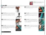
Slide a washer on the threaded bolt then 

slide this through the removal slug (1.5” long). Slide the tool assembly 

through the Dogbone, shock connection point. On the opposing side slide 
on the catch sleeve and washer, then thread the nut on. 

linkaGe DisassemblY


Place the wrenches on the tool assembly 

and turn to press the pin out.

frame DisassemblY


To remove the main pivot pin, place a 5mm 

allen key on the button head bolt and a 6mm allen key on the  pivot 

pin. Turn counter-clockwise until the button head is removed. Then take an 
8mm allen key and tap out the main pivot pin.

frame DisassemblY


To remove the shock mounting bolt, place on 

5mm allen key on both end of the bolt and turn counter-clockwise. 

One the male Yeti bolt is removed, take a 6mm allen key and tap out the 
female end.

note: 

this method works for all three mounting bolt s on a Fox Racing 

shock. For a 5th element see the specified section on the following page.

3

4

frame DisassemblY


First, take the two 5mm allen keys and loosen 

one of the male Yeti bolts. Remove the loosened Yeti bolt and set aside 

for reassembly. 

frame DisassemblY


Slide a 4mm allen key inside of the threaded 

steel pin and feel for the 4mm hex in the middle of the pin. Take the 

5mm allen key and turn counterclockwise against the 4mm allen key to 
break the assembly free. All the pieces to the seatstay pivot should now be 
loose and slide apart. 

1

2

5th element DisassemblY nOte 

The seatstay pivot has a unique disassembly technique. The 

system is made up of a steel female pin threaded on both side with a 4mm broach in the middle. Attached to 
this pin is two male Yeti bolts. Follow the instructions below to disassemble this pivot point. Also note there 
is a diagram of the steel pin below to aid in disassembly.

4mm broach

threaded ends

steel Pin DiaGram

1

2

Содержание AS-Rsl

Страница 1: ...Yeti Cycles 600 Corporate Circle Unit D Golden CO USA p 303 278 6909 888 576 9384 www yeticycles com...

Страница 2: ...ures 6 Geometry 8 Maintenance Schedule 10 Bike Setup Overview 12 Shock Setup FOX RP3 14 Quick Start Guide 15 Cable Routing 16 Assembly Overview 18 Assembly 20 Disassembly Tips 24 Exploded Views 26 Par...

Страница 3: ...inor injuries or damage to your bicycle or a component of your bicycle Be sure to read and understand all of the Warnings and Cautions Congratulations on your purchase of a new Yeti bicycle We are con...

Страница 4: ...bon Flex pivot allowed us to shave weight and increase performance I beam construction has great lateral stiffness yet smooth suspension performance 5 Shock 6 5 eye to eye 1 5 stroke 6 Dogbone Dogbone...

Страница 5: ...ork Xs S M L a 16 75 18 0 19 0 21 3 b 21 0 22 4 23 4 24 4 c 74 73 73 73 d 71 71 71 71 e 16 9 16 9 16 9 16 9 f 40 3 41 6 42 6 43 6 g 12 75 12 75 12 75 12 75 h 27 5 28 0 28 0 28 0 i 4 0 4 0 4 5 5 25 B G...

Страница 6: ...check out the repair help section This section contains detailed instruction on many of the service items listed in the maintenance schedule Torque YETI has outlined a brief list of torque specificati...

Страница 7: ...The shock should be returned to an Authorized Fox Racing Shox service center for repair To remove the shock from the linkage will require the Yeti linkage tool The linkage tool is necessary to proper...

Страница 8: ...the main spring air pressure To reduce sag increase the main spring air pressure Refer to the quick start guide to get your starting air pressure Sag Once you have set your baseline air pressure you n...

Страница 9: ...n the housing over the shock in to the stop on the seatstay Make sure there is enough housing so it does not bind on the shock body The last piece of housing in run from the second stop on the seatsta...

Страница 10: ...ps Make sure your tools are in good condition A worn allen key round the hex on a bolt not allowing for proper torque Torque settings are listed throughout the instructions It is also import to prep a...

Страница 11: ...to hold the shock assembly in place Swing the Dogbone into mounting position two Slide a 22mm female Yeti bolt and washer through the mounting hole Tap the 22mm female Yeti bolt into position with th...

Страница 12: ...lt with a washer on the opposing side of the female bolt and thread into position Cinch down both male Yeti bolts with the 5mm allen keys The last step is to install the derailleur hanger and water bo...

Страница 13: ...ounting bolt place on 5mm allen key on both end of the bolt and turn counter clockwise One the male Yeti bolt is removed take a 6mm allen key and tap out the female end Note this method works for all...

Страница 14: ...5 1 300030085 Main Pivot Pin 6 1 300030087 Steel Pin 1 38 7 2 300020025 Needle Bearing 8 2 300020001 Main Pivot Bearing 9 2 300020027 688 2RS Bearing 10 2 300020026 688 2rs W Ext Ring Bearing 11 2 300...

Страница 15: ...PIN 2 300030090 PIN 1 300030094 O RING 2 500050066 AS R 03 05 Rear Tri bearings not included 1 600000021 AS R FrontTri 1 500060016 AS R Dogbone Bearings 03 05 1 300020027 AS R 16MMX8MMX5MM BRG 688 2R...

Страница 16: ...5 ID X 687 OD X 3125 2 300020001 BEARING 6903 2 300030076 BOLT PIVOT FEMALE YETI CR MO 35 5 MM 1 300030077 BOLT PIVOT FEMALE YETI CR MO CP 24 8MM 2 300030078 BOLT PIVOT MALE YETI CR MO CP M6X17MM 3 3...

Страница 17: ...ented to an authorized Yeti dealer together with proof of purchase The above warranties have been in effect since January 2000 All Yeti frames sold prior to that date had a limited 1 one year warranty...

Отзывы: