


ML-x17 DATA LOGGER MANUAL
Manufacturers of low power instruments
page 99
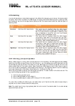
outer terminals is changing with the angle of the potentiometer. Very often potentiometers are used to
regulate a voltage from 0% to 100 % of the input voltage. In the next figure this well know circuit is drawn.
The output voltage is adjustable from 0% to 100% of Vin, in this case. The ML-x17 data logger has 3
terminals (on connector X1) for connecting a potentiometer to the logger:
X1.6 = GND
X1.7 = 0..100% Resistance
X1.8 = Resistance Reference terminal
So, the circuit above is connected as follows:
IN+ = X1.8
GND = - = X1.6
OUT = X1.7
Another application of the use of the potentiometer-input is to connect a PT-1000 temperature sensor to
the potentiometer-input. In the appendix is this example explained
The resistance reference terminal is derived from the internal ADC reference and has a 150-ohm
series resistor (to prevent damage in case of a wiring fault). The internal reference has a level of
3.30 Volts. When relative low impedance potentiometers are used, there will be a voltage drop
across the internal series resistor, and the max ADC value w
on’t be reached. Another reason to use only
high impedance potentiometers. Of course, when a sensor has got a low impedance value, you can use
it, but you have to compensate for the voltage-drop.


